4283
Evaluation of a high permittivity helmet for use as a coil former for an 8ch transmit/receive array with dodecahedral symmetry.1The Center for Advanced Imaging Innovation and Research (CAI2R), Department of Radiology, New York University School of Medicine, New York, NY, United States, 2The Bernard and Irene Schwartz Center for Biomedical Imaging, Department of Radiology, New York University School of Medicine, New York, NY, United States, 3The Sackler Institute of Graduate Biomedical Sciences, New York University School of Medicine, New York, NY, United States
Synopsis
A helmet shaped coil former made of high permittivity material is simulated with an 8 channel transmit/receive coil as an evaluation step towards coil construction. The addition of the high permittivity material improves performance in both transmit and receive but the choice of a permittivity that is too high may lead to undesired split-resonance effects.
Introduction
High-permittivity, low conductivity materials (HPMs) have been shown to improve coil performance in both transmission, by reducing specific absorption rate (SAR)1-4, and in reception, by improving signal-to-noise (SNR)1,2,5. Therefore transmit/receive coils may significantly benefit from the presence of a built-in HPM. However, when resonant RF coils are placed close to high permittivity materials, increased attention must be paid to the potential effects on coil performance. HPMs have been shown to affect tuning and coupling when placed close to RF coils6,7, and to potentially cause resonance splitting8. Here we evaluated in simulation whether the performance of an 8 channel transmit/receive helmet shaped coil with dodecahedral symmetry9 could be improved with the presence of a layer of HPM. Materials with different relative permittivities were tested in simulation, with the aim of designing an optimal HPM former for future coil construction. The original coil design placed the hardware at a 1cm distance from the head using padding, to ensure safety in transmit. This empty space was filled with a layer of high permittivity material in simulation to explore coil effects and evaluate performance benefit.Methods
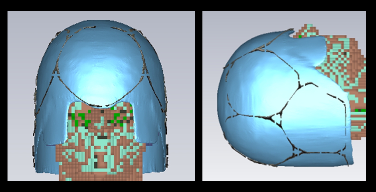
Simulations were performed using Microwave Studio (CST 2014, Darmstadt, Germany). A mesh model of the 8 channel head coil was imported into CST and placed around the Virtual Family “Duke” model10 [Figure 1]. A 1cm layer of HPM was modeled off of the helmet former for this coil, using 3-Matic Medical 11.0 (Materialize, Leuven Belgium), and three cases were evaluated: no HPM, the high-permittivity layer filled with water (ɛR = 78.4, σ = 0.00000555 S/m), and with a CaTiO3/water slurry (ɛR = 107, σ = 0.083 S/m)11. For each case the coils were tuned and matched for 7Tesla. SNR and B1+ were evaluated in order to assess the potential improvement provided by the presence of the HPM. For the evaluation of B1+, the coils were combined to generate a CP-like excitation by adjusting each coil’s excitation phase to create constructive interference in the center of the plane of interest.Results
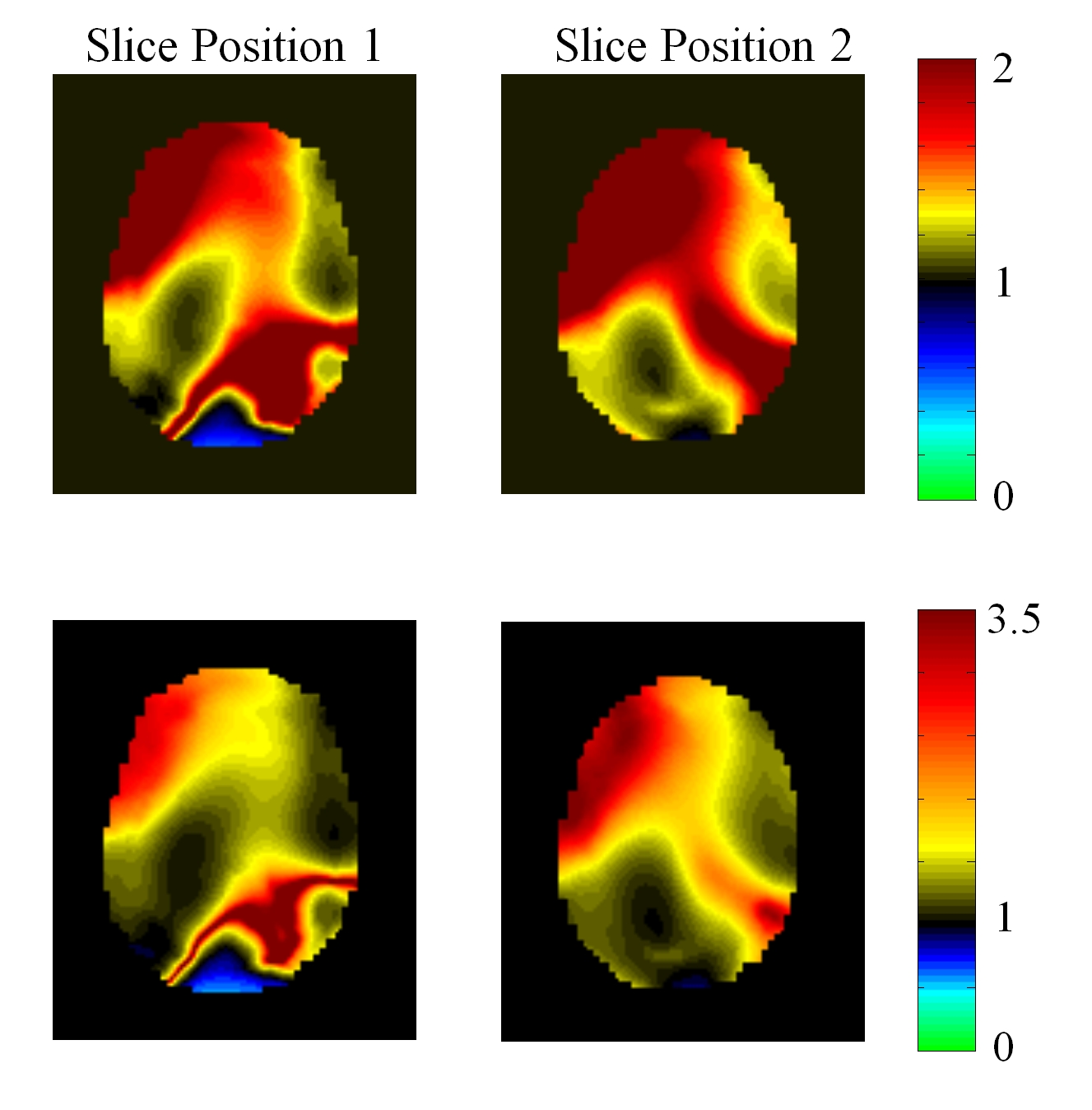
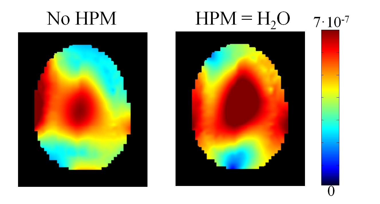
In the presence of the CaTiO3 HPM layer, split resonance effects made tuning the coils impossible7. Therefore the use of CaTiO3 with this coil design was determined to be impractical for future construction. In the presence of the water layer all coils could be sufficiently tuned, matched, and decoupled [Figure 2]. Coupling was affected by the presence of the HPM, but it was not increased to the point that nearest neighbor elements could not be capacitively decoupled. The presence of the HPM provided significant improvement in SNR [Figure 3], with gains of more than 350% over the coil alone [Figure 4]. There were areas in the brain where the presence of the HPM layer reduced SNR, but these regions were initially SNR-rich, so the effect was determined to not negate the net positive gains provided by the HPM. With B1+ normalized to the square root of absorbed power, the HPM case showed improved peak excitation at the center of the brain [Figure 5], with more than a 10% improvement of peak B1+/sqrt(Accepted Power).Conclusions
The presence of the high permittivity material drastically improves both transmit and receive performance of this coil. The dramatic increase in SNR is especially useful near the surface of the head, as the coil design is limited to 8 channels in receive. The presence of resonance splitting effects with higher permittivity values encourages the use of evaluating the combination of the former and the resonant coil structure in simulation before construction; the proximity of the HPM to the coil can create split resonance effects, especially for large coils, even with relative permittivity values as low as 107. Optimization of the thickness of the HPM layer, and construction of the coil with an HPM former will be explored in future work, as these results suggest that the addition of a layer of HPM would create significant performance benefits.Acknowledgements
The Center for Advanced Imaging Innovation and Research (CAI2R, www.cai2r.net) at New York University School of Medicine is supported by NIH/NIBIB grantnumber P41 EB017183.
This work additionally supported by NIH R01 EB021277
References
1) Webb, A. G. "Dielectric materials in magnetic resonance." Concepts in Magnetic Resonance Part A 38.4 (2011): 148-184.
2) Yang, Qing X., et al. "Reducing SAR and enhancing cerebral signal-to-noise ratio with high permittivity padding at 3 T." Magnetic resonance in medicine 65.2 (2011): 358-362.
3) Brink, Wyger M., and Andrew G. Webb. "High permittivity pads reduce specific absorption rate, improve B1 homogeneity, and increase contrast-to-noise ratio for functional cardiac MRI at 3 T." Magnetic resonance in medicine 71.4 (2014): 1632-1640.Collins et al. ISMRM 2014, p404.
4) Lattanzi et al. Effects of high-permittivity materials on absolute RF coil performance as a function of B0 and object size. ISMRM 22nd Annual Meeting, Milan, Italy; 10-16 May 2014, p4818.
5) Collins, Christopher M., and Qing X. Yang. Single configuration of coil and high-permittivity material improves performance for a wide range of subjects. ISMRM 22nd Annual Meeting, Milan, Italy; 10-16 May 2014, p404.
6) Zhang, et al. Evaluating the SNR performance of using dielectric pads with multiple channel RF coils at 7T. ISMRM 23rd Annual Meeting. Toronto, ON, Canada; 30 May - 5 June 2015; p1782.
7) Haemer, et al. Changes in neighbor and next-nearest-neighbor coupling of transmit/receive arrays in the presence of close-fitting high permittivity materials. ISMRM 23rd Annual Meeting. Toronto, ON, Canada; 30 May - 5 June 2015; p3104.
8) Haemer, et al. Discovering and working around effects of unwanted resonant modes in high permittivity materials placed near RF coils. ISMRM 23rd Annual Meeting. Toronto, ON; 30 May - 5 June 2015; p 859.
9) Haemer, et al. An 8 Channel Transmit Receive Helmet Coil with Dodecahedral Symmetry. ISMRM 21rd Annual Meeting. Salt Lake City, UT, USA; 20-26 April 2013; p 2749.
10) Christ, Andreas, et al. "The Virtual Family—development of surface-based anatomical models of two adults and two children for dosimetric simulations." Physics in medicine and biology 55.2 (2009): N23.
11) Luo, Wei, et al. "Permittivity and performance of dielectric pads with sintered ceramic beads in MRI: early experiments and simulations at 3 T." Magnetic resonance in medicine 70.1 (2013): 269-275.
Figures