4282
Alternative approach for modeling a geometrically complex RF coil for evaluation in simulation.1The Center for Advanced Imaging Innovation and Research (CAI2R), Department of Radiology, New York University School of Medicine, New York, NY, United States, 2The Bernard and Irene Schwartz Center for Biomedical Imaging, Department of Radiology, New York University School of Medicine, New York, NY, United States, 3The Sackler Institute of Graduate Biomedical Sciences, New York University School of Medicine, New York, NY, United States
Synopsis
An alternative approach for generating a digital model of an RF coil is described that avoids the use of geometric priors and ensures structural accuracy. This approach is demonstrated on a helmet-shaped transmit-receive coil, and the resulting simulations are compared to experimental data.
Introduction
Finite element models are an invaluable tool for calculating SAR and related safety risks for transmit/receive radio frequency (RF) coils1-4. However, in order to ensure safety limits5 are met, precision in the simulation and accuracy of both the geometry and the resulting fields of the coil must be ensured. While modeling coils in simulation is straightforward for models with simple geometric bases, such as cylindrecal or rectangular conductive elements, etc., more complex geometries can be difficult to accurately simulate. Here we describe an alternate method for generating a 3D voxelized model of an existing RF coil with a complicated geometry that guarantees geometric accuracy in simulation.Methods
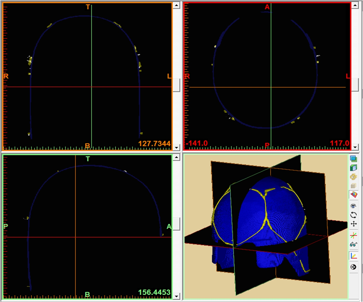
Previously an 8-channel transmit-receive coil was designed6 to fit tightly to a helmet modeled after a European head norm EN960/19947. The RF coil was built using wire to conform to the helmet, and preliminary testing showed improvement in both SNR and B1+ efficiency at the center of the brain with respect to a 1ch transmit, 24ch receive head coil (Nova Medical, Wilmington MA). However, because of the helmet’s shape, the structure could not be accurately represented by a combination of simple geometric initials, so an alternative approach to modeling the coil was developed. A CT scan (Siemens Biograph mCT, Erlangen Germany) of the completed coil was acquired (140kVp, 525mAs, Pitch 0.35mm, Resolution 0.58x0.58x0.6mm), and the DICOM data was exported in extended Hounsfield units and loaded into Mimics Medical 19.0 (Materialize, Leuven Belgium) for segmentation. Binary masks for the helmet former and the coil were derived separately, using the software’s thresholding algorithm, and manually editing was performed to remove streaking artifacts caused by capacitors [Figure 1]. Two volumes, of the former and coil model, were exported to Meshlab (Visual Computing Laboratory) where the binary voxel data was converted into a triangular mesh, additional smoothing was performed, and overlap between the helmet and the coil was removed. The finalized mesh was imported into CST (Microwave Studio 2014, Darmstadt Germany) in stl format and placed around the Virtual Family “Duke” model8 [Figure 2]. The mesh was defined with 2x2x2mm3 resolution within the coil, and meshing was visually evaluated to ensure efficacy of the stl import. Fixed capacitors were modeled to match those on the constructed coil, while variable capacitors were adjusted to create a match in coupling parameters between the coil and the simulation. Bench measurements were performed using a calibrated network analyzer (Agilent Technologies, E5061A) and a human head load. B1+ profiles for individual coils were analyzed and compared to those acquired in vivo using Actual Flip Angle Imaging9 and individual channel FLASH readouts (TR/TE/Flip/Slice/BW = 200ms/4.1ms/85°/4mm/300, FoV192x192x192, 48x48x48)10. Coils were combined using an approximately circularly polarized mode, by varying phase based on coil position, and peak 10g averaged SAR in the head was determined.Results
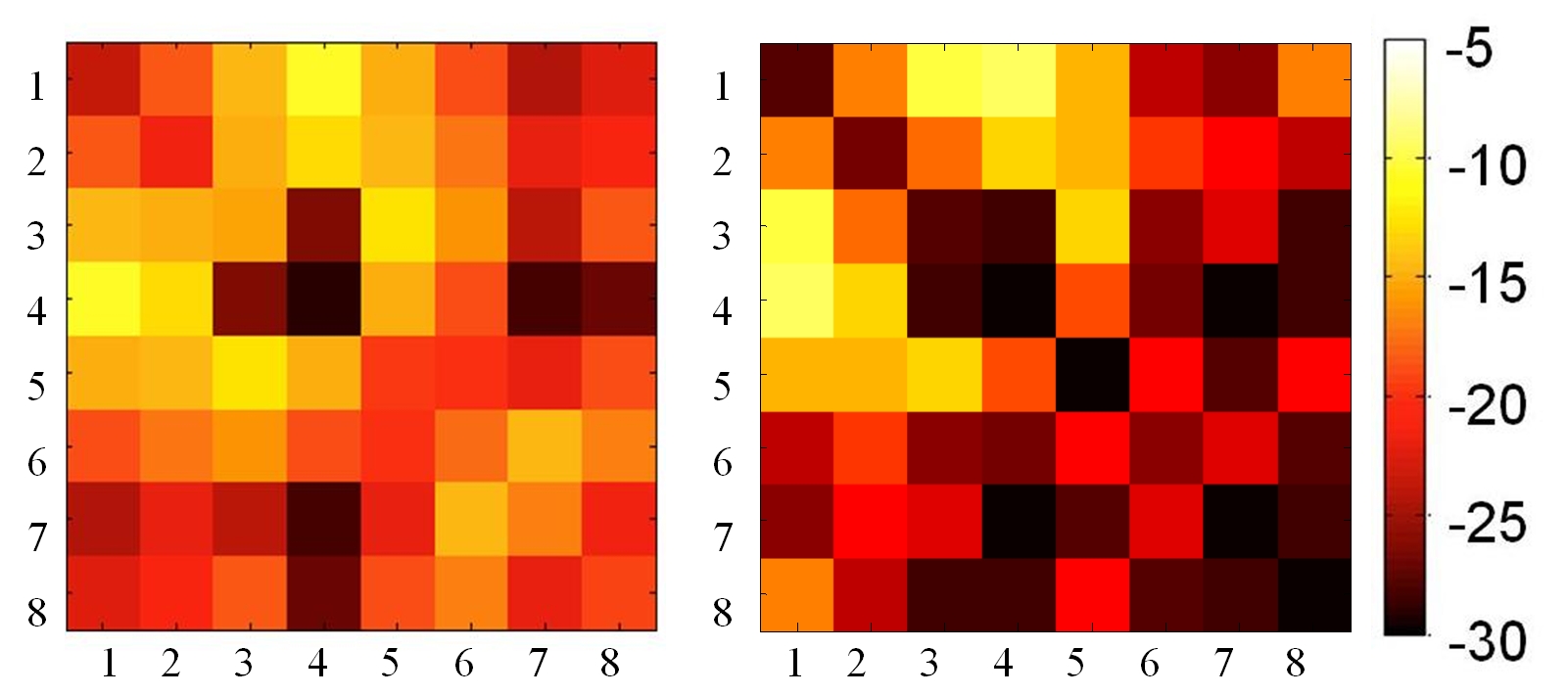
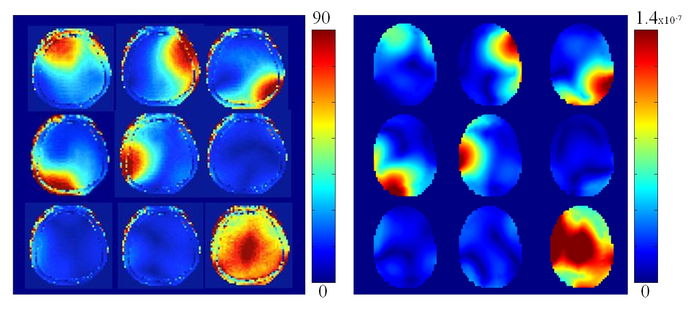
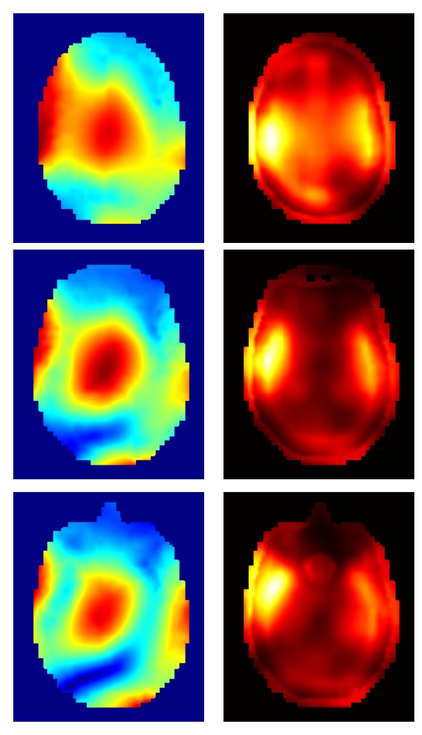
The model generated from the CT data aligned well with the CT images, and the resulting stl model of the coil demonstrated a good visual match to the constructed coil [Figure 2]. The model of the helmet former provided a guide to ensure that the rotation of the coil in respect to the bore was accurate. The coupling parameters in simulation were very closely matched to those found on the bench [Figure 3]. Decoupling on the simulated coil surpasses that of the original coil for the bottom three coils, numbered 6, 7, and 8, but does not appear to greatly otherwise affect coil performance. This difference can most likely be attributed to the increased load on the bottom three coils provided by the Duke model. The B1+ profiles of the resulting individual coils matched closely to those found in vivo [Figure 4]. Figure 5 shows a SAR map and corresponding B1+ of a circularly polarized mode from the simulated model.Conclusions
We described a novel method to generate an accurate 3D numerical model of an existing coil with complex geometry for simulation based on a simple CT scan of the coil. The use of 3D visualization toolboxes and editing software to verify geometry allowed for a very accurate model of complicated 3D wire trajectories making up the coil structure. The accuracy of the model was confirmed by the matching of both coupling parameters and B1+ profiles to those seen experimentally. This model will be used in future work for safety and performance evaluation of the constructed coil.Acknowledgements
The Center for Advanced Imaging Innovation and Research (CAI2R, www.cai2r.net) at New York University School of Medicine is supported by NIH/NIBIB grantnumber P41 EB017183.
This work additionally supported by NIH R01 EB021277
References
1) Collins, Christopher M., Shizhe Li, and Michael B. Smith. "SAR and B1 field distributions in a heterogeneous human head model within a birdcage coil." Magnetic resonance in medicine 40.6 (1998): 847-856.
2) Ibrahim, T. S., et al. "B1 field homogeneity and SAR calculations for the birdcage coil." Physics in medicine and biology 46.2 (2001): 609.
3) Graesslin, Ingmar, et al. "A specific absorption rate prediction concept for parallel transmission MR." Magnetic resonance in medicine 68.5 (2012): 1664-1674.
4) Zhu, Yudong, et al. "System and SAR characterization in parallel RF transmission." Magnetic resonance in medicine 67.5 (2012): 1367-1378.
5) International Electrotechnical Commission. International standard, medical electrical equipment—Part 2–33: particular requirements for the basic safety and essential performance of magnetic resonance equipment for medical diagnosis, 3rd ed. International Electrotechnical Commission 601–2–33, Geneva: International Electrotechnical Commission; 2010.
6) Haemer, et al. An 8 Channel Transmit Receive Helmet Coil with Dodecahedral Symmetry. ISMRM 21rd Annual Meeting. Salt Lake City, UT, USA; 20-26 April 2013; p 2749.
7) British Standards Organization. Head forms for sure in testing of protective helmets. London: British Standards Organization; 1995.
8) Christ, Andreas, et al. "The Virtual Family—development of surface-based anatomical models of two adults and two children for dosimetric simulations." Physics in medicine and biology 55.2 (2009): N23.
9) Yarnykh, Vasily L. "Actual flip-angle imaging in the pulsed steady state: a method for rapid three-dimensional mapping of the transmitted radiofrequency field." Magnetic resonance in Medicine 57.1 (2007): 192-200.
10) Amadon, et al. Validation of a very fast B1-mapping sequence for parallel transmission on a human brain at 7T. ISMRM 20th Annual Meeting. Melbourne, Victoria, Australia; 5-11 May 2012; p3358.
Figures