4281
The Twisted Solenoid RF Phase Gradient Transmit Coil for TRASE Imaging1Physics, University of Alberta, Edmonton, AB, Canada, 2Oncology, University of Alberta, Edmonton, AB, Canada
Synopsis
TRASE is a k-space encoding method that uses RF transmit phase gradient fields to achieve mm-level resolution. However, image quality is critically dependent upon the efficient generation of B1 fields with uniform magnitude and strong phase gradients. We present a new family of phase gradient coil designs based upon a solenoid twisted about a transverse axis. Four twisted solenoids wound on a single cylindrical former are sufficient to encode two spatial dimensions. The design has many attractive geometric, electrical and magnetic characteristics, including the ability to encode in the B0-direction, previously not possible for transverse-B0 magnet geometries.
Purpose
TRASE (Transmit Array Spatial Encoding) is a k-space encoding method that exploits RF transmit phase gradient fields to achieve mm-level resolution1-3. The encoding pulse sequence consists of a train of 180° refocusing pulses. The phase gradient transmit field is switched between each RF pulse, in an alternating pattern. Since the conventional gradient encoding system may be replaced by a switched RF transmit array, TRASE is a promising technique for low field, low cost MRI systems4. Such low cost systems often employ permanent magnets, exhibiting a transverse magnetic field. This presents a need for new designs because there is currently no practical TRASE transmit design for encoding along the B0 direction for this transverse B0 geometry. Secondly, in TRASE there is an ongoing need for improved coil designs because image quality is largely determined by the ability to efficiently generate and switch B1 fields with uniform magnitude and strong phase gradients.Twisted Solenoid Design Concept and Aims
The design concept was to exploit and retain all the desirable features a solenoid coil has for a transverse B0 field (i.e., high efficiency (uT/A)), uniformity, large imaging FOV relative to aperture), while introducing a twist to the coil-winding pattern to generate a phase gradient in a transverse axis (along B0). Other key design constraints are: a |B1| uniformity over the FOV within +/- 10%, and a strong and linear phase gradient (3 … 5 deg/mm).Design and Methods
Accordingly, we present a new family of phase gradient coil designs based upon a solenoid twisted about a transverse axis (Fig.1). The wire lies on the parametric curve:
$$P_x(\theta) = a \cos(\theta)$$
$$P_y(\theta) = a \sin(\theta) $$
$$P_z(\theta) = A \sin(2\theta+\phi) + (h/2\pi)\theta$$
where a is the coil radius; A the twist amplitude (controlling the phase gradient strength); $$$\phi$$$ the winding shift; and h determines the turn advance5. For a thin wire, tightly wound coil (current sheet approximation) of radius a and infinite length with its axis along the z–axis, current I, the B field components within the aperture, in cylindrical coordinates $$$(\rho, \theta, z)$$$ are5:
$$B_\rho = - \mu_0 \frac{I}{h} \frac{A\rho}{a^2}\sin(2\theta+\phi)$$
$$B_\theta = - \mu_0 \frac{I}{h} \frac{A\rho}{a^2}\cos(2\theta+\phi)$$
$$B_z = - \mu_0 \frac{I}{h}$$
Analyses using this analytical solution were performed. Also, Biot-Savart simulations of practical coil designs were performed5. These duplicated the general features of the current sheet solution, but include effects of finite length and finite turns. In this low frequency regime (8.2 MHz for 0.2T) Biot-Savart simulations provide a good approximation.
Results
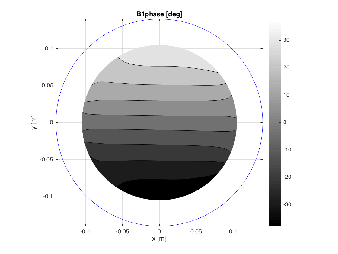
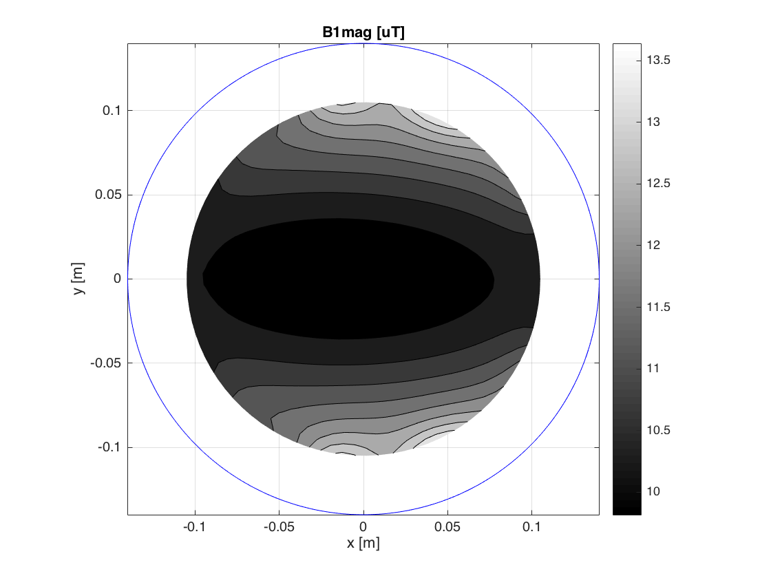
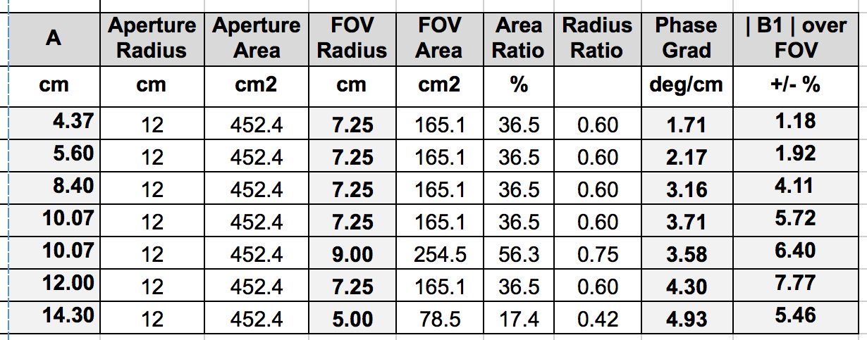
Almost the entire aperture of the coil exhibits a uniform phase gradient, which is an excellent result. As expected3, there is a tradeoff between phase gradient strength and B1 homogeneity (i.e. usable imaging FOV), see table. The twisted solenoid coils are highly efficient, having an |B1| efficiency (uT/Amp) only slightly lower (10% …15%) than a pure solenoid, and much higher (x2 .. x3) than a comparable Helmholtz-Maxwell design3. This |B1| efficiency equates to shorter refocusing pulses, reduced T2 resolution losses, better off-resonance performance, and a substantially reduced RF peak power requirement. This also compensates for a slightly lower (typically 75%) phase gradient strength relative to a Helmholtz-Maxwell design (for equal internal aperture).Discussion
The twisted solenoid coil has a large number of attractive characteristics. It is notable that the B1 phase gradient direction is determined solely by the RF coil geometry, not by the B0 direction. This allows the four gradient fields necessary for 2D encoding (+GX,-GX,+GZ,-GZ) to be produced by a set of identical coils, oriented at different rotation angles about the patient axis (Y). Geometrically, the coil is compact, being wound on a cylindrical former, offering an open unobstructed aperture, a large fraction being useable as the imaging volume; also the coils can be of any length. Electrically, the single current path simplifies PIN diode coil enable/disable circuitry. Since only a single element is needed for each phase gradient (rather than two3) each element may be driven with a separate RF power amplifier (RFPA), providing several advantages, including lower RFPA peak power; elimination of power combiner / splitter and phase shifter circuitry3; and better duty cycle performance.Conclusions
Twisted solenoid RF coils are a new type of compact and efficient phase gradient coil designs for TRASE imaging in transverse B0 field magnets. By selection of depth of modulation, coil orientation, number of turns and turn density a family of phase gradient coils may be designed. In conjunction with a 1D Helmholtz-Maxwell coil, the twisted solenoid makes full 3D TRASE encoding practical.Acknowledgements
Departments of Oncology and Physics, University of Alberta.References
1. Sharp, J.C., King, S.B MRI using radiofrequency magnetic field phase gradients Magn. Reson. Med. 63(1) 151-161, 2010.
2. Sharp, J.C., King, S.B. Deng, Q. Volotovskyy, V. Tomanek, B. High-resolution MRI encoding using radiofrequency phase gradients NMR in Biomedicine 26(11), Nov 2013, Pages 1602-1607
3. Deng, Q, King, S.B., Volotovskyy V., Tomanek B., Sharp J.C.; B1 transmit phase gradient coil for single-axis TRASE RF encoding Magn. Reson Imag. 31(6), 891–899 (2013)
4. Stockmann, J.P , Cooley, C.Z, Guerin, B., Rosen, M.S, Wald, L.L. Transmit Array Spatial Encoding (TRASE) using broadband WURST pulses for RF spatial encoding in inhomogeneous B0 fields. J. Magn. Reson. Vol 268, 1 July 2016, Pages 36-48
5. L. Quéval, R. Gottkehaskamp, Analytical Field Calculation of Modulated Double Helical Coils,.; IEEE Trans on Applied Superconductivity, 4901307, 25(6) Dec 2015 6. L. Quéval, “BSmag Toolbox User Manual,” Tech. report, Dept. Elect. Eng., University of Applied Sciences Du¨sseldorf, Germany, April 2015. Available: http://www.lqueval.com [Accessed April. 07, 2015]. https://www.mathworks.com/matlabcentral/fileexchange/52680-magnetic-field-of-modulated-double-helical-coils
Figures
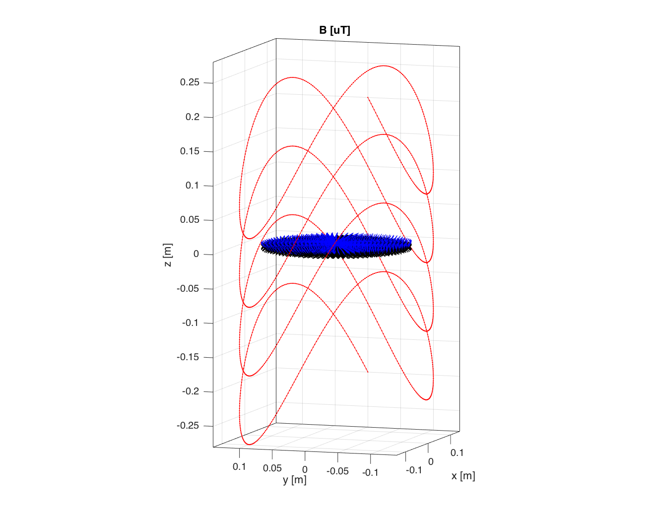
Figure 1. Twisted solenoid TRASE phase gradient coil. (Parameters: A=0.1007, radius,a = 14cm; h= 0.1; 4 turns; I = 1 Amp). B0 is in the y-direction. The blue disk indicates the position of the field plots, shown in Figs. 2 & 3.