4280
Visualizing the role of ideal current patterns in minimizing sample noise using dark mode current patterns for a spherical sample1Center for Advanced Imaging Innovation and Research (CAI2R), Department of Radiology, New York University School of Medicine, New York, NY, United States, 2Bernard and Irene Schwartz Center for Biomedical Imaging, Department of Radiology, New York University School of Medicine, New York, NY, United States, 3Sackler Institute of Graduate Biomedical Sciences, New York University School of Medicine, New York, NY, United States
Synopsis
We show that the ideal surface current patterns maximizing internal signal-to-noise ratio (SNR) are composed of a) signal-optimizing current patterns which maximize the signal sensitivity without considering sample noise, and b) “dark mode” current patterns which minimize sample noise without affecting signal. For a central voxel in a spherical sample, the absence of dark mode current patterns on an encircling sphere suggests that optimally tracking the precessing spin while ignoring sample noise is sufficient to achieve the best possible SNR. For an off-center voxel, however, the dark mode current patterns form high magnitude localized currents that efficiently minimize sample noise.
PURPOSE
To evaluate different contributions of current modes comprising ideal current patterns resulting in optimal signal-to-noise ratio (SNR) at different locations in a spherical sample. Signal-only optimal current patterns (OP patterns) efficiently track a precessing spin, using the least possible current to maximize signal sensitivity at the voxel of interest (1). Whereas the OP patterns are calculated by ignoring sample noise (2,3), ideal current patterns simultaneously minimize sample noise to achieve the ultimate intrinsic signal-to-noise ratio (UISNR) (4). By comparing the two current patterns, we can separate the effect of optimizing for signal only or for SNR at a particular voxel. To investigate how the ideal current patterns specifically minimize sample noise, we study the dark mode current patterns, which are found by subtracting the OP patterns from the full SNR-optimizing ideal current patterns.METHODS
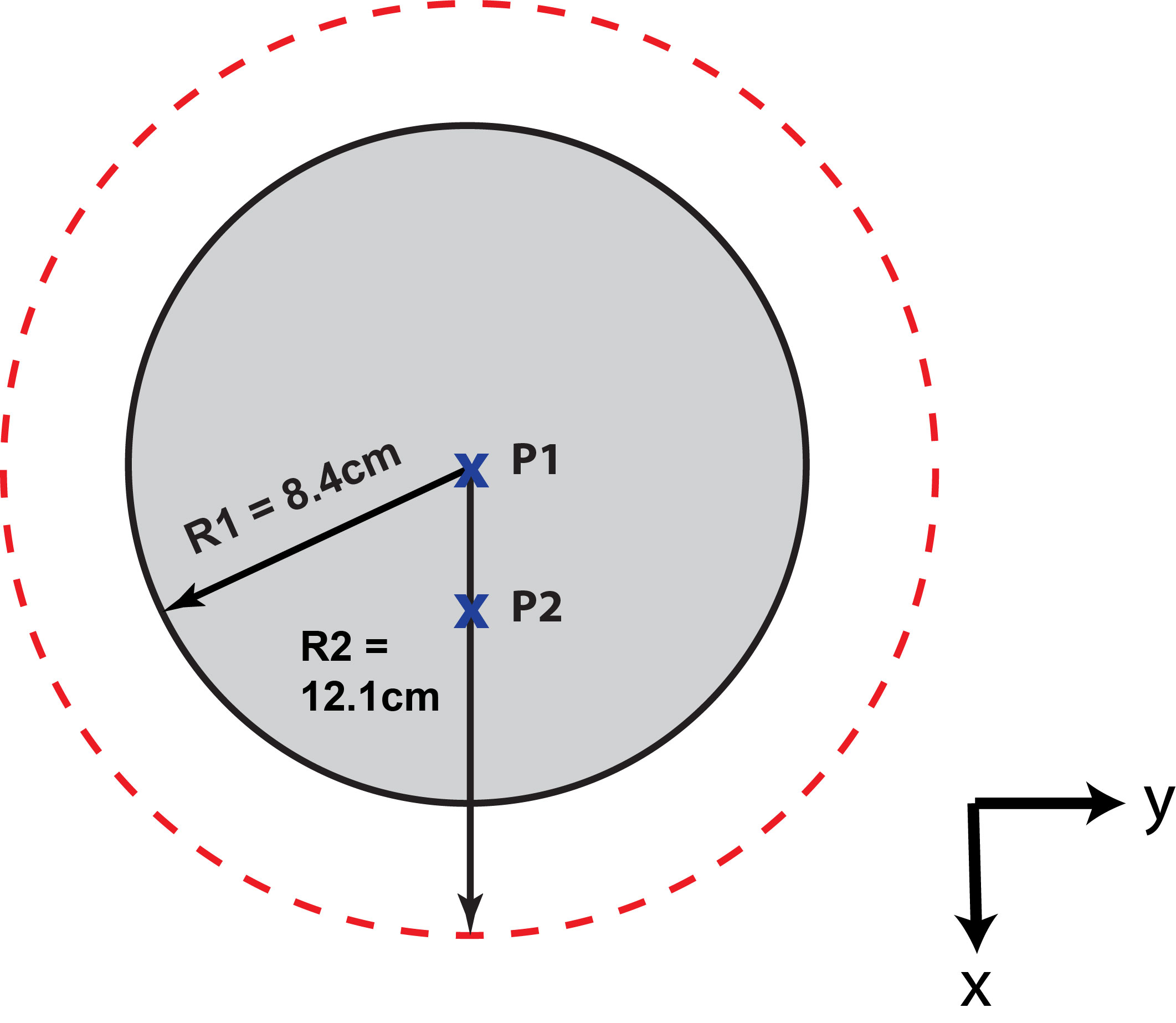
An in-house analytical simulation framework based on dyadic Green’s functions (DGF) (4) was used to calculate all current patterns and corresponding fields for two voxels in a uniform spherical sample at the proton Larmor frequency corresponding to 1 T and 7 T (Fig 1). To optimally combine the basis set of current modes to obtain the UISNR, the weights for the ideal current patterns (WICP) were calculated as follows (4): $$$W_{ICP}=\left(S^{H}\psi_{mode}^{-1}S\right)^{-1}S^{H}\psi_{mode}^{-1}$$$where S is the sensitivity matrix and ψmode is the noise correlation matrix of the modes. The weights for the OP patterns (WOP) were calculated by setting the noise correlation matrix in the above equation to a multiple of the identity, thus ignoring sample noise in the optimization, while penalizing any added currents (and associated conductor noise). The dark mode weights (WDM), which corresponded to zero signal sensitivity, were obtained as follows: $$$W_{DM}=W_{ICP}-W_{OP}$$$. The electric (E) field and the signal sensitivity (B1(-)) corresponding to each set of current patterns were calculated by weighting the ultimate basis set of E fields and B1(-) fields associated with each current mode. Sample noise was calculated as the square root of $$$\int\sigma E\cdot E^{\star}dv=W\psi_{mode}W^{H}$$$ . A mode expansion of order lmax = 45 was used to ensure convergence of the field calculations.RESULTS AND DISCUSSION
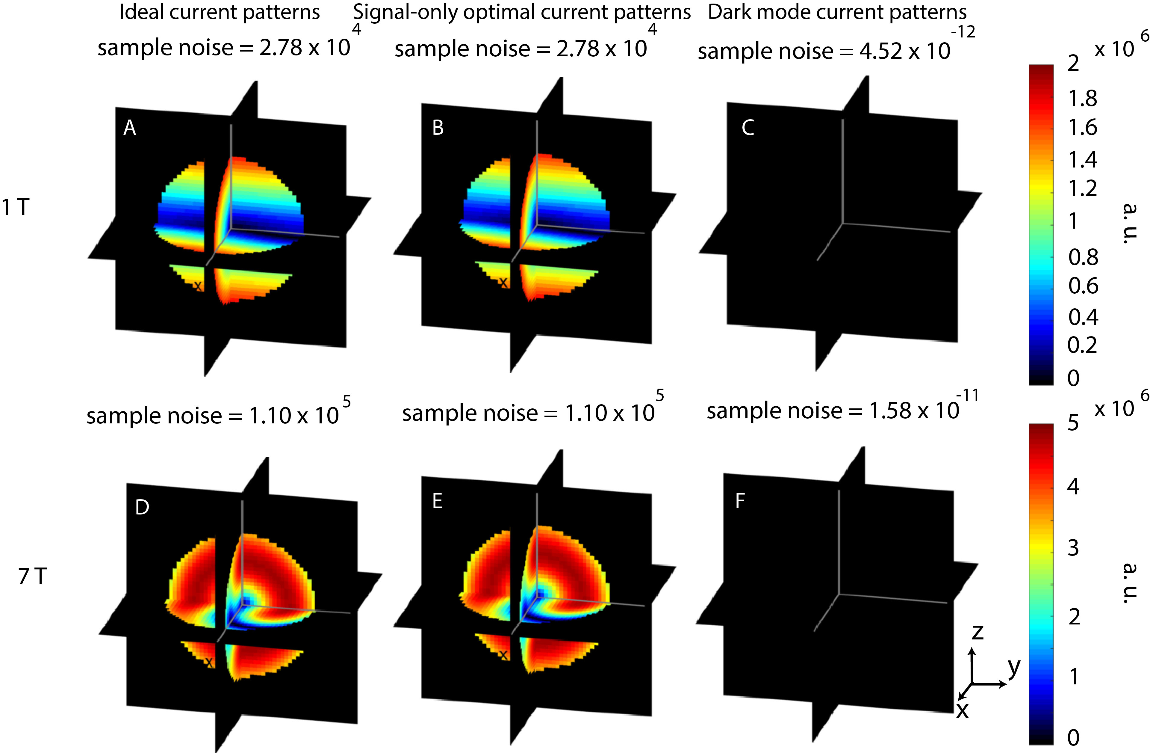
For all cases, the B1(-) associated with the ideal current patterns and the OP patterns was equal to one for the voxel of interest. The B1(-) corresponding to the dark mode current patterns was equal to zero, which validated that the dark mode current patterns are not sensitive to signal at the voxel of interest. For a central voxel, ideal current patterns and OP patterns were equivalent, and formed two distributed loops that rotated around the sphere at the Larmor frequency (Fig 2: A, B, D, E). The rotational phase delay of the current patterns between the two field strengths was likely due to increased propagation delay from the center to the surface at 7 T (Fig 2: A vs. D). The dark mode current patterns (Fig 2: C, F), and the corresponding E field and sample noise (Fig 3: C, F), were essentially absent for a central voxel, which indicated that no noise minimization occurred. Since only one basis mode contributes to the signal sensitivity at the center of a spherical sample (5), our result suggested that the only optimization possible to obtain the UISNR is to closely track the precessing spin for efficient signal reception. This is a straightforward manifestation of the Optimality Principle recently identified as an intuitive means of deriving ideal current patterns (1). For an off-center voxel, the ideal current patterns and dark mode current patterns formed a distributed figure-eight and loop with high magnitude currents localized near the position of the voxel (Fig 4). The magnitude of the OP patterns in this case was notably less than that of the ideal current patterns and the dark mode current patterns (Fig 4: B, G vs. A, F and C, H), which achieve E field and sample noise reduction as compared to the signal-only case (Fig 5) via localized higher magnitude currents near the voxel of interest.CONCLUSIONS
The absence of dark mode current patterns for a central voxel in a uniform spherical sample suggests that the UISNR can be achieved with current patterns that simply track the precessing spin and ignore sample noise. For an off-center voxel, maximizing signal sensitivity alone is not sufficient. As seen in the dark mode current patterns, high magnitude currents localized near the voxel are required to minimize sample noise sensitivity and thereby to achieve the UISNR.Acknowledgements
This work was supported by the Center for Advanced Imaging Innovation and Research (www.cai2r.net), a NIBIB Biomedical Technology Resource Center (NIH P41 EB017183).References
1. Sodickson DK, Lattanzi R, Vaidya MV, Chen G, Novikov DS, Collins CM, Wiggins GC. The Optimality Principle for MR signal excitation and reception: New physical insights into ideal RF coil design. Proceedings of the International Society for Magnetic Resonance in Medicine, April 2017, Hawaii:submitted.
2. Sodickson DK, Wiggins GC, Chen G, Lakshmanan K, Lattanzi R. More Than Meets the Eye: The Mixed Character of Electric Dipole Coils, and Implications for High-Field Performance. Proceedings of the International Society for Magnetic Resonance in Medicine, May 2016, Singapore:pg. no. 0389.
3. Vaidya MV, Collins CM, Sodickson DK, Carluccio G, Lattanzi R. Disentangling Signal Propagation and Noise-Related Effects in the Presence of High Permittivity Materials Via Ideal Current Patterns. Proceedings of the International Society for Magnetic Resonance in Medicine, May 2016, Singapore:pg. no. 0391.
4. Lattanzi R, Sodickson DK. Ideal current patterns yielding optimal signal-to-noise ratio and specific absorption rate in magnetic resonance imaging: computational methods and physical insights. Magn Reson Med 2012;68(1):286-304.
5. Lee H, Sodickson DK, Lattanzi R. An analytic expression for the ultimate intrinsic SNR in a uniform sphere. Proceedings of the International Society for Magnetic Resonance in Medicine, April 2017, Hawaii:submitted.
6. Gabriel C, Gabriel S. Compilation of dielectric properties of body tissues at RF and microwave frequencies. http://niremf.ifac.cnr.it/docs/DIELECTRIC/home.html and http://niremf.ifac.cnr.it/tissprop/. 1996.
Figures