4087
Integrated setup and characterization of an MRI-compatible PET camera for preclinical ultra-high field imaging1Buffalo Neuroimaging Analysis Center, Department of Neurology, Jacobs School of Medicine and Biomedical Sciences, University at Buffalo, The State University of New York, Buffalo, NY, United States, 2SynchroPET, Inc., Stony Brook, NY, United States, 3MRI Clinical and Translational Research Center, Jacobs School of Medicine and Biomedical Sciences, University at Buffalo, The State University of New York, Buffalo, NY, United States
Synopsis
Simultaneous Positron Emission Tomography (PET) and Magnetic Resonance Imaging (MRI) in small animals would enable entirely new approaches to drug development and yield to a better functional understanding of living organisms. However, preclinical systems that allow truly simultaneous PET and MRI are not yet commercially available. We present the integration of an optimized microPET camera with ultra-high magnetic field strength MRI.
PURPOSE
Simultaneous PET-MRI is a promising technology to combine the strengths of two powerful imaging modalities. The benefit of clinical PET-MRI is currently under investigation and preclinical hybrid systems that allow sequential PET and MRI at medium field strengths (3 Telsa) have recently become commercially available (Bruker, MedioUSA)1. However, technology for truly simultaneous PET-MRI (like in humans) for the preclinical setting has not yet made its way beyond the proof-of-concept stage2. In the present work, we present a modular integration of a new prototype PET camera that can be retrofitted into any preclinical MRI system and investigate mutual interferences between the device and MRI at 9.4T.METHODS
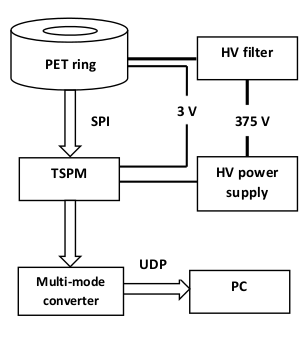
Equipment: The prototype PET system (SynchroPET, Inc.; Stony Brook, NY) is based on a previously presented platform3, consisting of 12 scintillator crystals (LYSO,18.5x9.6x6mm3,4x8 pixels), APD and ASICS microchips (Fig.1). Experiments were performed at a preclinical 9.4T MRI (Bruker Biospin, Biospec 94/20 USR) equipped with a 440 mT/m imaging gradient insert with 114 mm inner diameter and a volume transceiver coil (outer/inner diameter=44/23mm).
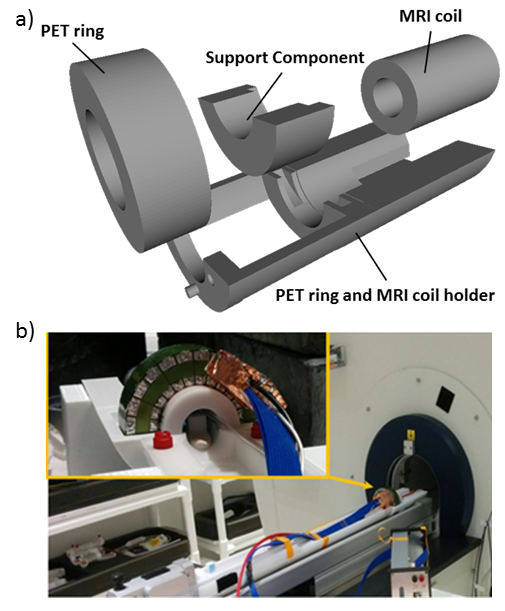
Integration: We designed (FreeCAD v0.16) and 3D-printed (Stratasys Eden 260V;VeroWhite) an attachable integration module for the MRI’s motorized sample positioning system (AutoPAC,Bruker Biospin) that holds PET ring and RF coil (Fig.2).
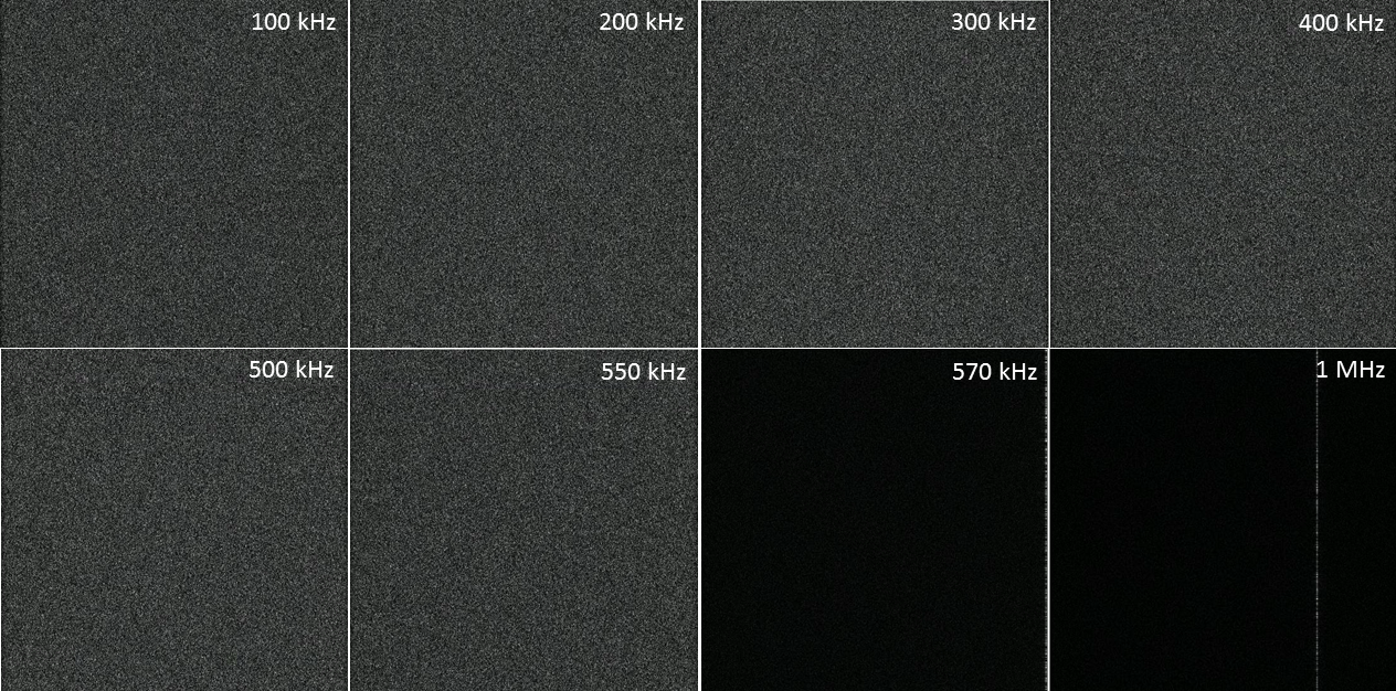
Experiments: Despite physical independence of the imaging mechanisms, interactions between the two modalities include induced magneto-static inhomogeneities of the main magnetic field (B0), electromagnetic interactions of the PET electronics with RF pulses and rapidly switching imaging gradients. We studied effects of PET on MRI performance in three configurations: MRI-only and PET-MRI with PET powered off/on. For MRI we used a glass sphere phantom filled with CuSO4-doped water (9mm diameter) positioned in the center of the RF coil. The protocol included: PRESS (TR/TE=2500/20ms;averages = 1,no water suppression) after iterative linear shimming process to assess field inhomogeneity; 2D-T1-RARE (TR/TE=1500/8.5ms,factor=4,slice-thickness=2mm,voxel-size=100x100µm2,excitation/refocusing pulse-power=18/63W), a 2D-T2-SE (TR/TE=283.8/8.6ms,slice-thickness=1.5mm,voxel-size=105x105µm2,excitation/refocusing pulse-power=18/63W), a 2D-FLASH (TR/TE=350/5.4ms,flip=40º,slice-thickness=0.5mm,voxel-size=80x78µm2,pulse-power=20W), a 3D-multi-echo-GRE (TR/TE1=22.5/1.33ms,ΔTE=1.50ms,10 echoes,flip=7º,FOV=20x20x20mm3,200µm isotropic,bandwidth=357kHz,pulse-power=11W,78% duty-cycle) and a noise-dedicated 2D-FLASH without RF excitation pulse (TR/TE=350/5.4ms,FOV=55x55mm2,slice-thickness=0.5mm,voxel-size=100x100µm2, readout bandwidths: 100 kHz,200 kHz,300 kHz,400 kHz,500 kHz,550 kHz,570 kHz,and 1 MHz). To assess the high-resolution MRI performance we applied a 3D FLASH sequence (80µm isotropic, bandwidth=50 kHz,pulse-power=128 W) to a Gadolinium-perfused rat brain immersed in a perfluoropolyether (GaldenHT80). Effects of MRI on PET were investigated using a 50μCi Na-22 point source (0.23mm diameter;Eckert&Ziegler) in five configurations: PET outside magnet without/with coil, PET inside magnet without/with coil (no MR imaging), and PET inside magnet with coil (active MR imaging).
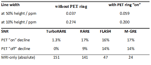
Analysis: We compared MRI images acquired in different settings side-by-side with respect to image artifacts and SNR. Static field inhomogeneities were assessed by calculating the water-line width. For PET experiments, we assessed the scintillation counts per second in each setting for 10 minutes.
RESULTS
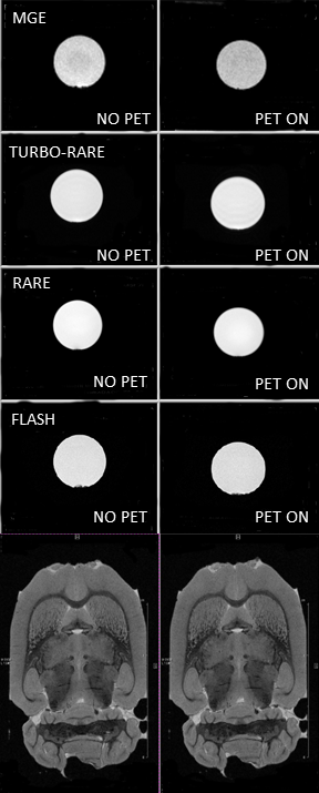
Using the custom-designed integration module Fig.2), a transition of the experimental setup from conventional MRI-only to hybrid PET-MRI was achieved in less than 15 minutes. Field homogeneity was not significantly decreased, but SNR was reduced between 0 and 14% compared to the MRI-only setting when the PET ring was installed and powered off and between 1.3 and 17% when the PET camera was powered on (Table I). The comparison of MR images acquired with and without PET ring (powered on) did not reveal differences in image quality (Fig.3). The noise-dedicated scans showed a single-line zipper artifact when the PET camera was powered on and a readout bandwidth wider than 550 kHz was used (Fig.4). Prompt counts per second decreased by 12% when the MRI coil was inserted into the PET camera and increased by 12% with active MRI.DISCUSSION
The electromagnetic interactions between PET and MRI imaging are sufficiently small to permit advanced MR imaging with simultaneous PET. In particular, no MRI artifacts were observed for typically used readout bandwidths. The measured decrease in SNR, while it may require slightly longer acquisition times, will not be a limiting factor in most applications. Most importantly, the shimming algorithm was able to correct field homogeneities associated with the installed PET camera, an essential requirement for techniques such as MRS, DTI, and fMRI. The increase of the PET count rate during MRI acquisition can be addressed software-wise by removing counts during RF pulsing by analyzing the coincidence rate over time.CONCLUSION
This study presented a modular integration concept and demonstrated the MRI-compatibility of a novel prototype micro-PET camera that may be retrofitted to any commerical preclinical MRI system. The availability of a truly simultaneous PET-MRI imaging technology for preclinical applications sets the stage for entirely new functional, metabolic and pharmacokinetic research approaches in rodent models of diseases.Acknowledgements
This work was supported in part by the University at Buffalo Center for Advanced Biomedical and Bioengineering Technology (UB CAT) and by the National Center for Advancing Translational Sciences of the National Institutes of Health under award Number UL1TR001412. The content is solely the responsibility of the authors and does not necessarily represent the official views of the NIH.References
1. Nagy, Kálmán, et al. "Performance evaluation of the small-animal nanoScan PET/MRI system." Journal of Nuclear Medicine 54.10 (2013): 1825-1832.
2. Vandenberghe, Stefaan, and Paul K. Marsden. "PET-MRI: a review of challenges and solutions in the development of integrated multimodality imaging." Physics in medicine and biology 60.4 (2015): R115.
3. S. H. Maramraju, S. D. Smith, S. S. Junnarkar, D. Schulz, S. Stoll, B. Ravindranath, M. L. Purschke, S. Rescia, S. Southekal, J.-F. Pratte, P. Vaska, C. L. Woody, and D. J. Schlyer, “Small animal simultaneous PET/MRI: initial experiences in a 9.4 T microMRI.” Physics in medicine and biology, vol. 56, no. 8, pp. 2459–80, 2011.
Figures