4044
A Fast Multi-Contrast Knee Imaging Method Using a Hybrid bSSFP Pulse Sequence1Electrical Engineering, KAIST (Korea Advanced Institute of Science and Technology), Daejeon, Korea, Republic of
Synopsis
To increase the contrast between the bone and the cartilage, fat saturation techniques are additionally applied to the conventional imaging sequences. However, the fat saturation techniques eliminate most of the bone information. Thus, using the modified bSSFP (balanced steady-state free precession) pulse sequence called a hybrid bSSFP pulse sequence, the proposed method offers the multi-contrast knee images with very short imaging time (< 10 sec).
Introduction
Magnetic resonance imaging (MRI) technology offers the most important diagnostic information for bone and cartilage of the knee, in comparison to other imaging modalities (1). To increase the contrast between the bone and the cartilage, fat saturation techniques are additionally applied to the conventional imaging sequences. However, the fat saturation techniques eliminate most of the bone information. Thus, using the modified bSSFP (balanced steady-state free precession) pulse sequence called a hybrid bSSFP pulse sequence, this abstract proposes a fast imaging method which can make various image contrasts between the bone and the cartilage.Methods
The bSSFP pulse sequence offers a good signal-to-noise ratio (SNR) with a short TR, so that imaging time can be substantially reduced. Thus, it is steadily applied to knee imaging (2, 3). The acquired signal from bSSFP pulse sequence is combination of free-induction-decay (FID) signal and echo signal. The MR signal from the conventional bSSFP pulse sequence is derived as follows (4),
$${\bf M} =({\bf I}-{\bf R} {\scriptsize \alpha} {\bf Q})^{-1}(1-{\it E} {\scriptsize 1}){\bf R} {\scriptsize \alpha}{\bf M} {\scriptsize 0},\tag1$$
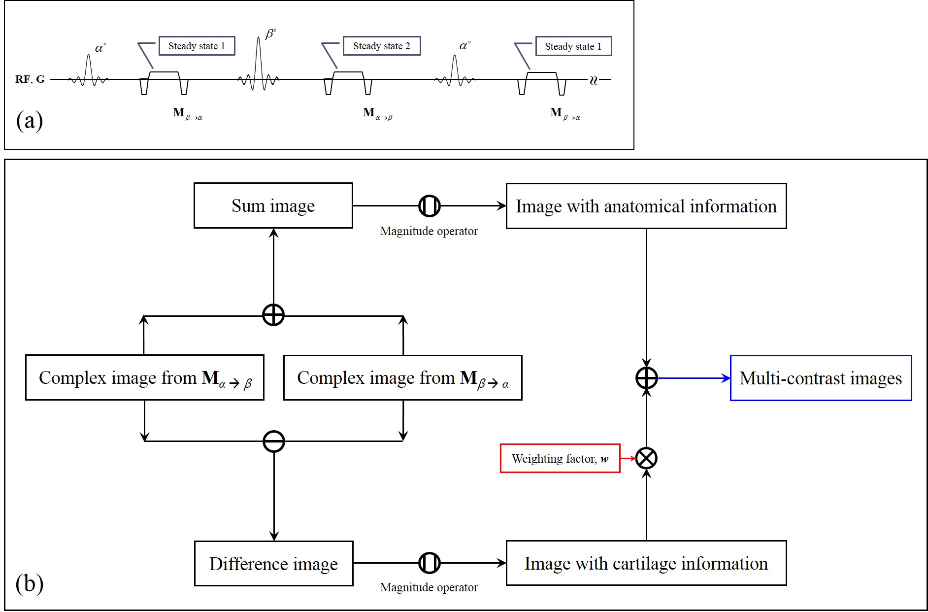
where M is the magnetization vector just after the RF pulse, M0 is the initial magnetization vector, Rα is the rotation matrix due to the α° RF pulse, Q is the precession and T2-relaxation matrix, E1 is defined as exp(-t/T1). If the RF flip angle becomes close to the Ernst angle, the FID signal increases. The larger RF flip angle is applied (close to 180°), the larger signal in the transverse plane is refocused. Thus, in the proposed method, by using the alternating RF flip angles, the amount of the FID signal and the echo signal at each TR period are manipulated, as shown in Fig. 1(a). The proposed method is composed of two RF pulses having different flip angles. Then, the MR signals from alternating RF pulses are formulated, respectively, as follows,
$${\bf M} {\scriptsize \beta\rightarrow\alpha}=({\bf I}-{\bf R} {\scriptsize \alpha} {\bf Q}{\bf R} {\scriptsize \beta}{\bf Q})^{-1}(1-{\it E} {\scriptsize 1}){\bf R} {\scriptsize \alpha}({\bf Q}{\bf R} {\scriptsize \beta}+{\bf I}) {\bf M} {\scriptsize 0}\\{\bf M} {\scriptsize \alpha\rightarrow\beta}=({\bf I}-{\bf R} {\scriptsize \beta} {\bf Q}{\bf R} {\scriptsize \alpha}{\bf Q})^{-1}(1-{\it E} {\scriptsize 1}){\bf R} {\scriptsize \beta}({\bf Q}{\bf R} {\scriptsize \alpha}+{\bf I}) {\bf M} {\scriptsize 0},\tag2$$
where Mβ→αand Mα→β are the magnetization vectors just after the α° and β° RF pulses, respectively, and Rβ is the rotation matrix due to the β° RF pulse. Then, the proposed method makes two contrast images acquired just after two different RF pulses, respectively. Especially, the difference image between two contrast images provides cartilage-weighted information under small flip angles. In contrast, the sum image of two contrast images has anatomical information similar to conventional bSSFP contrast. So, the weighted combination of the sum and the difference images can make various contrast images. The schematic process of the proposed method is described in Fig. 1(b).
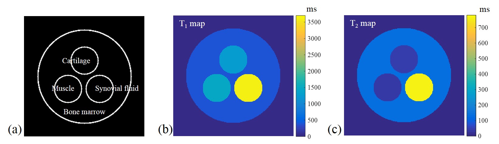
The simulations were performed using the phantom (Fig. 2(a)), which was composed of the cartilage, muscle, synovial fluid, and bone marrow (fat). The T1 and T2 values for composed materials were determined by the references (5) and (6), as shown in Fig. 2(b) and 2(c). The simulation parameters were determined as follows: TR/TE = 5.0/2.5 ms, flip angles = 7° and 10° with Gaussian random noise. In-vivo experiments were also performed using a 3 T MRI scanner (Siemens Magnetom Verio, Erlangen, Germany) to validate the proposed method. Imaging parameters were given as field of view (FOV) = 165×165 mm2, matrix size = 256×256, TR/TE = 5/2.5 ms, and number of averages = 5. For comparison, turbo spin-echo (TSE) proton-density (PD) images with/without fat saturation were acquired with TR/TE = 3200/37 ms.
Results
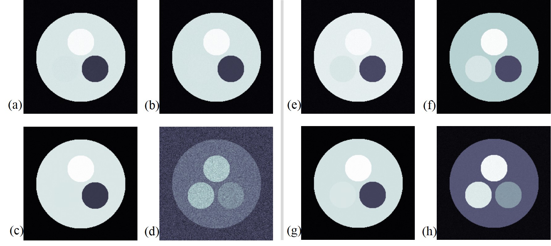
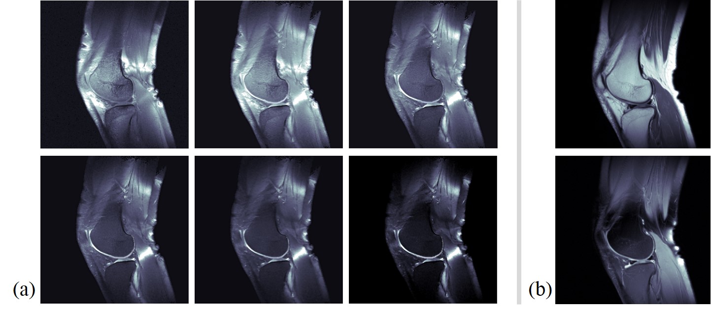
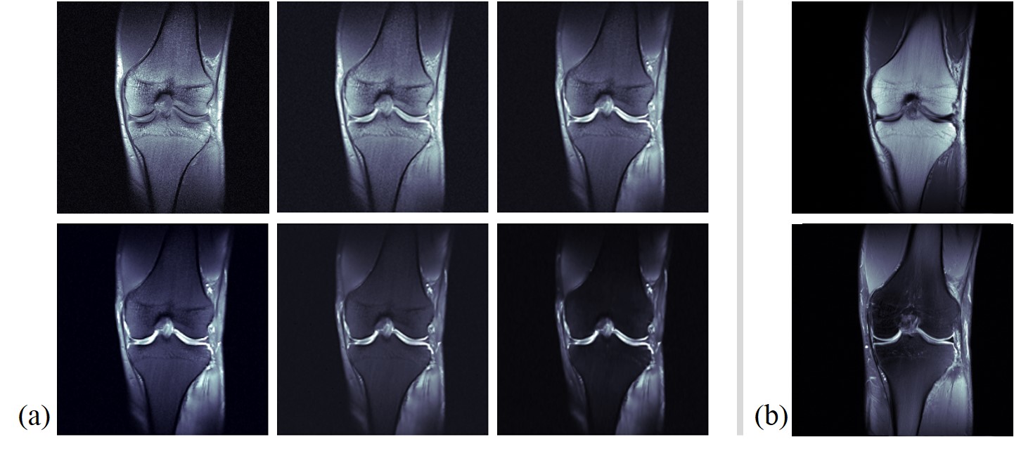
Figure 3 shows the simulation results. Figures 3(a) and 3(b) are images acquired from the conventional bSSFP signals defined as Eq. [1], which have flip angles of 7˚ and 10˚, respectively. Then, the difference image in Fig. 3(d) is noisy. Figures 3(e-h) are images acquired from the proposed method. The sum image in Fig. 3(g) is similar to conventional bSSFP images in Figs. 3(a) and 3(b), and the cartilage signal looks brighter at the difference image, as shown in Fig. 3(h). The in-vivo results are presented in Figs 4 and 5. Figures 4 (a) and 5(a) are the multi-contrast images from the proposed method with sagittal and coronal planes, respectively. The weighting factor, w, increases from the left-top image to right-bottom image. Figures 4(b) and 5(b) are the PD images without/with fat saturation for comparison.Conclusion and Discussion
As demonstrated by the simulations and the in-vivo experiments, the proposed method offers the multi-contrast knee images with very short imaging time (< 10 sec). By changing w, the proposed method offers various contrasts for the bone and the cartilage in the knee. Thus, it will be useful tool for diagnosis, such as the cartilage segmentation and fast screening.Acknowledgements
This research was supported by the Brain Research Program through the National Research Foundation of Korea (NRF) funded by the Ministry of Science, ICT & Future Planning (2014M3C7033999). This work was also supported by a grant of the Korea Health Technology R&D Project through the Korea Health Industry Development Institute (KHIDI), funded by the Ministry for Health and Welfare, Korea (HI14C1135).References
1. Radiographics 2011;31:37-62.
2. Magn Reson Med 2003;49:700-709
3. J Magn Reson Imaging 2007;25:270-278.
4. Springer-Verlag 1999; Magnetic Resonance Imaging Theory and Practice.
5. Am J Roentgenol 2004;183:343-351.
6. Magn Reson Med 2005;54:507-512.
Figures