4020
A Two-Dimensional Spiral Turbo-Spin-Echo Technique with T2-delay Correction and Concomitant Phase Compensation1Imaging Research, Barrow Neurological Institute, Phoenix, AZ, United States, 2Neuroradiology, Barrow Neurological Institute, Phoenix, AZ, United States
Synopsis
Turbo spin-echo (TSE) is a rapid technique routinely used for T2 and FLAIR imaging. Two-dimensional spiral TSE is very challenging due to T2 signal decay. In this project we develop a 2D spiral TSE sequence employing a spiral-in/out readout for efficient acquisition without off-resonance phase errors, and a double encoding mechanism as well as signal demodulation to minimize T2 signal decay induced artifacts. A concomitant phase compensation technique is incorporated to mitigate the violation of the CPMG condition. Preliminary spiral TSE FLAIR results demonstrate comparable image quality to its Cartesian counterpart.
Introduction
Turbo spin echo (TSE)1 employing fluid attenuated inversion recovery (FLAIR) is commonly used in the clinic for the diagnosis of many neurological diseases. Implementing spiral acquisition in a 2D TSE sequence results in swirl-like artifacts due to T2 signal decay. Additionally, the conventional use of spiral-out readout in TSE either introduces off-resonance phase errors, or does not optimize the sampling efficiency2. To overcome these issues, we develop a 2D TSE technique employing a spiral-in/out readout with a T2 decay correction mechanism. Furthermore, a compensation technique3,4 is incorporated to minimize the concomitant phase error that causes the violation of the CPMG condition. The feasibility of the proposed technique is illustrated in vivo with FLAIR imaging.Methods
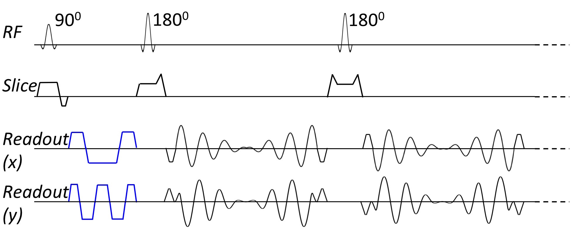
The spiral-in/out readout was incorporated into the 2D TSE sequence (Fig. 1), similar to a previously proposed 3D TSE technique2. The spiral-in/out readout inherits high scan efficiency from the conventional spiral-out readout but avoids its characteristic off-resonance phase errors2.
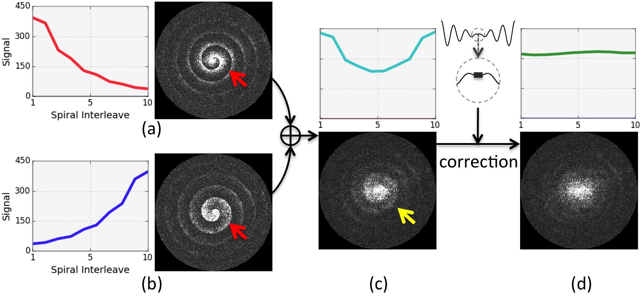
Double Encoding: In 2D TSE, different spiral arms are encoded by different echoes, thus adding a rapid signal modulation in k-space (Fig. 2a, red curve in the plot, or bright-gray pattern shown in the k-space image), which converts to swirl-like artifacts in images. To mitigate these artifacts, we propose a double encoding mechanism (i.e. 2 NSA), with each acquisition encoding the spiral arms in opposite directions (Figs. 2a and 2b). The two encodings are added together to reduce T2 signal decay induced signal modulation (Fig. 2c). To further minimize the signal modulation, extra calibration data are acquired at the center of k-space between the spiral-in and the spiral-out readouts. These data are used to estimate and then correct for residual signal modulation, which minimizes the signal variation (Fig. 2d).
Concomitant Phase Compensation: Another issue is that additional phase due to concomitant field arising from the spiral gradient will accumulate at the spin echo. This violates the CPMG requirement and causes artifacts4. The reference pre-scan5 can not correct for this phase error in non-axial 2D scans. To alleviate this issue, we incorporate the quadratic nulling method3,4 by using additional gradients (Fig. 1, gradients in blue color), which approximate the self-squared terms4 of the concomitant phase induced by the spiral-in gradient. The cross terms due to the spiral gradient are relatively small and not taken into account in this implementation. This largely cancels out the phase accumulation at the spin echo, mitigating the violation of the CPMG condition. These gradients are also flow compensated. A 1-2-1 flow compensation scheme is used on one axis (x) and a 1-2-2-2-1 scheme is used on the other axis (y) to minimize the cross terms arising from the overlapping concomitant phase compensation gradients themselves.
The sequence was implemented on a Philips 3T Ingenia scanner. Axial spiral data with FLAIR were acquired using the following parameters: FOV = 230x230 mm2, resolution = 0.9x0.9 mm2, 20 slices with 4 mm thickness and 2 mm gap, refocusing RF flip angle = 180˚, TR = 9000 ms, TI = 2500 ms, ETL = 10, 30 spiral interleaves with ADC = 18.3 ms, TE=137 ms. The reference Cartesian FLAIR was scanned with similar parameters except for FOV = 230x200 mm2, refocusing RF flip angle = 120˚, ETL = 34. Fat saturation was used in all scans. The scan time was 2:06 for both scans. Sagittal data were also acquired to demonstrate the efficacy of the concomitant phase compensation method.
Results and Discussion
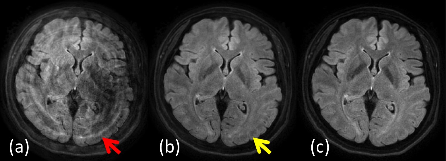
Fig. 3 shows the performance of the proposed double encoding mechanism and the additional signal demodulation, demonstrating its capability in minimizing the swirling artifacts. The signal demodulation is effective with FLAIR since the T2 values of white and gray matters are very close. It can be less optimal with T2-weighted TSE due to the very different T2 value of the CSF.
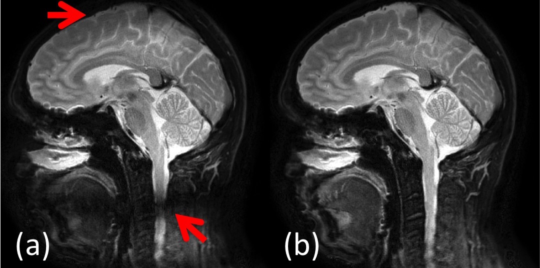
As shown in the sagittal images (Fig. 4), without concomitant phase compensation, there is signal loss at off-center voxels (Fig. 4a), which is minimized when the compensation technique is employed (Fig. 4b).
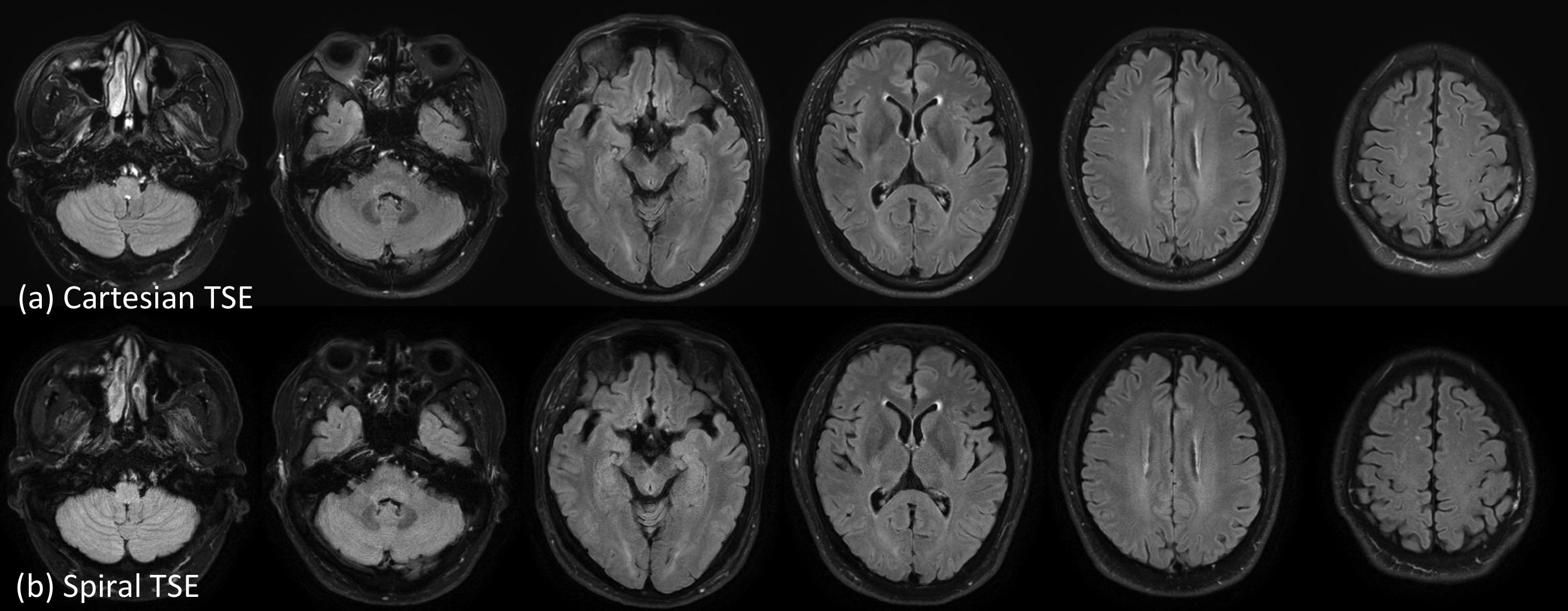
Fig. 5 compares the reference Cartesian with the spiral results. The spiral images exhibit comparable image quality as their Cartesian counterparts.
In this work, although a double encoding mechanism is used to compensate/correct for the signal variation, the total scan time is still comparable to that of Cartesian TSE due to the efficient spiral sampling pattern.
Conclusion
The preliminary results demonstrate a promising 2D Spiral TSE technique with efficient data sampling, effective correction for the T2 decay induced signal variation, and effective concomitant phase compensation.Acknowledgements
This work was funded by Philips Healthcare.References
(1) Hennig J, Nauerth A, Friedburg H. RARE Imaging: A Fast Imaging Method for Clinical MR. Magn Reson Med. 1986;3:823-833.
(2) Li Z, Wang D, Robison RK, et al. Sliding-Slab Three-Dimensional TSE Imaging With a Spiral-In/Out Readout. Magn Reson Med. 2016;75:729-738.
(3) Zhou XJ, Du YP, Bernstein MA, et al. Concomitant Magnetic-Field-Induced Artifacts in Axial Echo Planar Imaging. Magn Reson Med. 1998;39:596-605.
(4) Zhou XJ, Tan SG, Bernstein MA. Artifacts Induced by Concomitant Magnetic Field in Fast Spin-Echo Imaging. Magn Reson Med. 1998;40:582-591.
(5) Hinks RS. Fast Spin Echo Prescan for MRI System. US5378985 (A), 1995.
Figures