4018
Sliding Slice 2D Spiral Time of Flight MRA1MR Technology Design Group, Barrow Neurological Institute, Phoenix, AZ, United States
Synopsis
The scan technique and reconstruction method presented in this work are designed to reduce the scan duration of 2D time-of-flight angiography sequences. The acquisition makes use of a sliding-slice technique that eliminates the need for steady-state prep pulses, which are needed before each slice in time-of-flight. This reduces the total scan time of a 2D spiral time-of-flight sequence by almost half, without a reduction in k-space coverage.
Purpose
The scan technique presented in this work is designed to reduce the scan
duration of 2D time-of-flight (ToF) angiography sequences. The acquisition
makes use of a sliding-slice technique (similar to those described in [1] and
[2]) for the purpose of eliminating the excitations required to reach steady
state (start-up cycles) while maintaining T1 saturation in static tissue via a
slice-to-slice overlap. The acquisition also uses a spiral k-space trajectory [3,
4] to further reduce the acquisition duration (compared to standard Cartesian
acquisitions) [5]. The spiral technique is combined with a unique interleave
ordering [6] to minimize motion related artifacts and fat-water out-of-phase
imaging [7, 8] to minimize the appearance of fat signal. Purpose
Theory
Theory
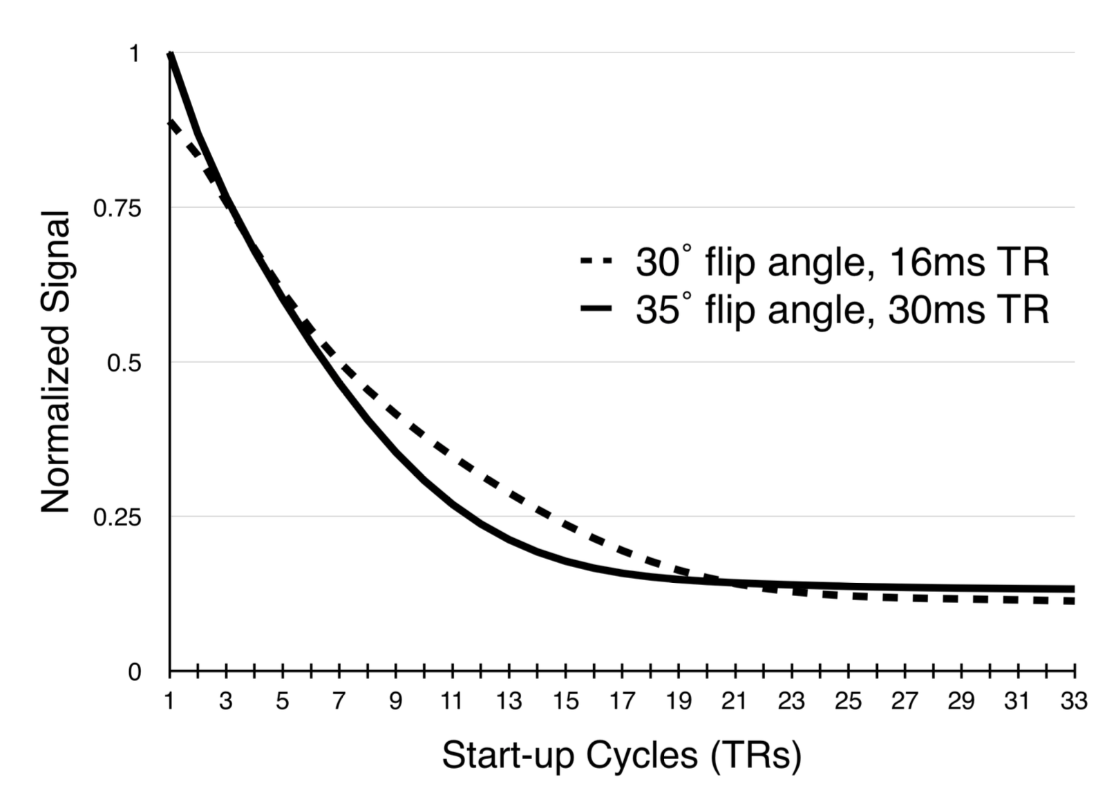
In spiral scans, as the sampling window is increased, fewer spiral acquisitions are needed to fully sample k-space, however, the number of start-up cycles needed to achieve steady state remains about the same (figure 1), leaving a larger portion of the scan duration to segments that aren’t acquiring data. The approach to steady is potentially more important to spiral sequences since each interleave samples the center of k-space (figure 2). The proposed sliding-slice technique creates a sliding window of overlapping slice excitations to maintain the saturation of static signal in the majority of the imaging plane while incrementally introducing fresh magnetization at the leading edge of the window.
In the sliding-slice technique, each spiral encode is sampled at a fraction of the slice-to-slice spacing ($$$\Delta_s$$$). As the spiral encoding index is incremented, the slice location is advanced by a step of $$$\Delta_s/m$$$, where $$$m$$$ is the number of spiral encodes. This small shift in slice location creates a small overlap of each slice with its neighbor and works to incrementally saturate the static tissue at the leading edge of each slice.
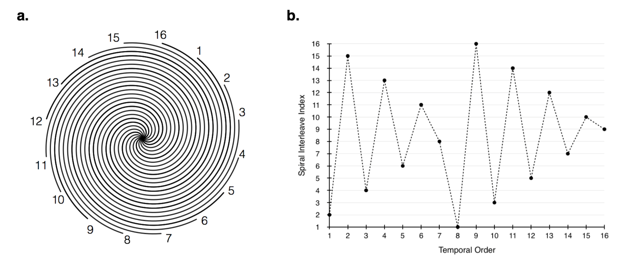
Each interleave $$$j$$$ (figure2(a)) will belong to a group that is shifted by $$$\Delta_s/m · j$$$ in the slice direction. The group will have the same in-plane k-space sampling, therefore, the shifts can be undone by applying the correct linear phase in the Fourier domain of the slice dimension.
The spiral index ordering (figure 2(b)) was chosen to minimize the effects of motion related artifacts by collecting the spiral interleaves in a way that minimizes the coherence of temporally varying signal, as described in [6]. This indexing pattern only affects the in-plane spiral order. The slices advance with the temporal indexing so that the sliding-slice transitions smoothly.
Methods
Methods
Scan Parameters: The proposed method was compared to conventional spiral and Cartesian methods for 2D multi-slice imaging of the carotid bifurcation. All scans were performed on a volunteer using a 3T Philips Ingenia system with a $$$17$$$-channel head and neck coil.
Cartesian: The standard Cartesian parameters used were: $$$TR/TE=16/3.2$$$ msec, $$$20x20$$$ cm in-plane field of view (FOV), $$$3$$$ mm slice thickness with a $$$1$$$ mm slice-to-slice overlap, $$$80$$$ slices, $$$30^◦$$$ flip angle, a sampling window of $$$3.7$$$ msec and flow compensation gradients. Three Cartesian sets were collected with fully sampled k-space, and SENSE reduction factors of $$$R=2$$$, and $$$R=3$$$.
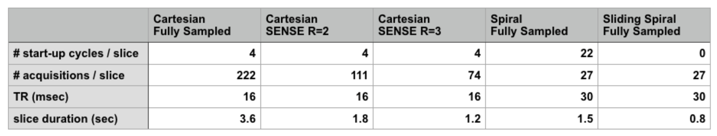
Spiral: The spiral scan parameters were: $$$TR/TE=30/3.5$$$ msec, $$$24x24$$$ cm FOV, $$$35^◦$$$ flip angle, a sampling window of $$$10.6$$$ msec, $$$27$$$ spiral interleaves, $$$3$$$ mm slice thickness with a $$$1$$$ mm slice-to-slice overlap, and $$$80$$$ slices with flow compensation gradients in the slice select direction. Two spiral sets were collected, with and without, the sliding-slices technique. Figure 3 shows the timing composition for each experiment.
Steady State: Two small spiral experiments were used to determine steady state for the aforementioned experiments, wherein the magnitude of the first sampled point of each spiral was plotted against the repetition number. The subject was a bottle of tap water.
Results & Discussion
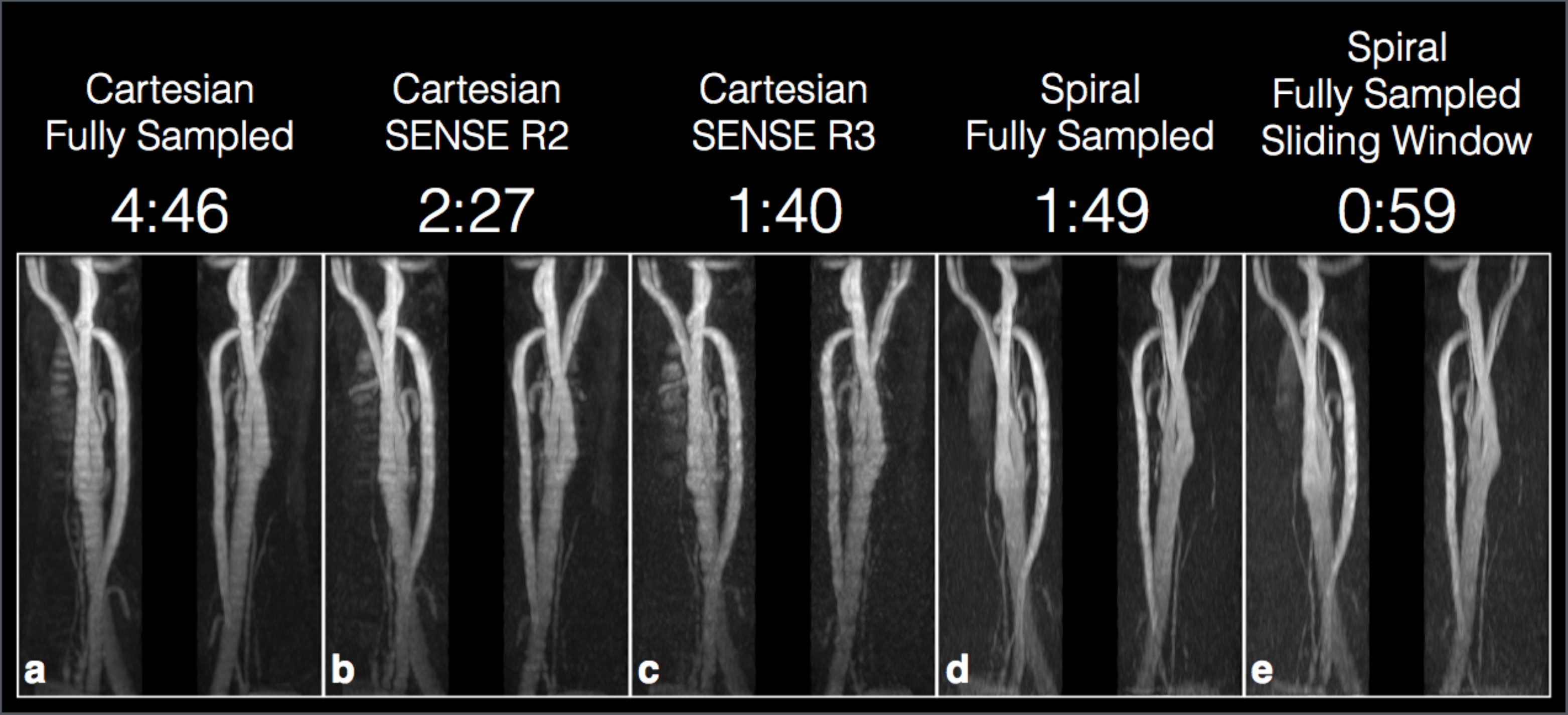
A reconstructed image for each experiment is shown in figure 4. The
proposed method (e) appears to show similar contrast and resolution to the
standard spiral sequence (d) with a slightly lower SNR. Overall the depiction
of the carotid bifurcation in (e) appears comparable to the other techniques.
The acquisition duration for each slice is significantly reduced using spiral
trajectories when compared to the fully sampled Cartesian sequence. The use
of a sliding-slice to replace the start-up cycles yielded a significant reduction
in total scan time compared to the standard spiral technique.Results & Discussion
Conclusion
A method for substantially reducing the total scan time of 2D ToF sequences
was presented. The proposed method is able to achieve this reduction in scan
duration without sacrificing k-space coverage.Conclusion
Acknowledgements
No acknowledgement found.References
[1] Jurgen Hennig. “Overlapping section coverage in multisection imaging”. In: Journal of Magnetic Resonance Imaging 3.2 (1993), pp. 425–432.
[2] Kecheng Liu and Brian K Rutt. “Sliding interleaved kY (SLINKY) acquisition: a novel 3D MRA technique with suppressed slab boundary artifact”. In: Journal of Magnetic Resonance Imaging 8.4 (1998), pp. 903– 911.
[3] James G Pipe and Nicholas R Zwart. “Spiral trajectory design: A flexible numerical algorithm and base analytical equations”. In: Magnetic Resonance in Medicine 71.1 (2014), pp. 278–285.
[4] JG Pipe and RK Robison. “Simplified signal equations for spoiled gradient echo MRI”. In: Proceedings of the International Society of Magnetic Resonance in Medicine. Stockholm 3114 (2010).
[5] Craig H Meyer et al. “Fast spiral coronary artery imaging”. In: Magnetic Resonance in Medicine 28.2 (1992), pp. 202–213.
[6] James G Pipe, Ergun Ahunbay, and Padmanabhan Menon. “Effects of interleaf order for spiral MRI of dynamic processes”. In: Magnetic resonance in medicine 41.2 (1999), pp. 417–422.
[7] Qing-San Xiang and Li An. “Water-fat imaging with direct phase encoding”. In: Journal of Magnetic Resonance Imaging 7.6 (1997), pp. 1002– 1015.
[8] NR Zwart, DH Wang, and JG Pipe. “Spiral Time of Flight MRA with Dixon Water and Fat Separation”. In: Proceedings of the International Society of Magnetic Resonance in Medicine. Singapore 1834 (2016).
Figures