3959
Fast Interrupted Steady-State (FISS) Magnetic Resonance Imaging1Radiology, NorthShore University HealthSystem, Evanston, IL, United States, 2Radiology, University of Chicago Pritzker School of Medicine, Chicago, IL, United States, 3Radiology, Northwestern University Feinberg School of Medicine, Chicago, IL, United States
Synopsis
We report an imaging approach, Fast Interrupted Steady-State (FISS), for retaining the high signal associated with true fast imaging with steady-state free precession (TrueFISP), while lessening its sensitivity flow artifacts.
Introduction
Fast low angle shot (FLASH)1 and true fast imaging with steady-state free precession (TrueFISP)2 are techniques frequently used in the clinical setting. Respective strengths of FLASH and TrueFISP imaging include robustness against off-resonance artifact and high signal-to-noise efficiency. However, well-known limitations of FLASH include saturation effects from slow flow, while limitations of TrueFISP include artifacts from off-resonance as well as from acceleration and flow. The purpose of this work is to report an imaging scheme, Fast Interrupted Steady-State (FISS) that combines the desirable properties of TrueFISP and FLASH while avoiding their weaknesses.Methods
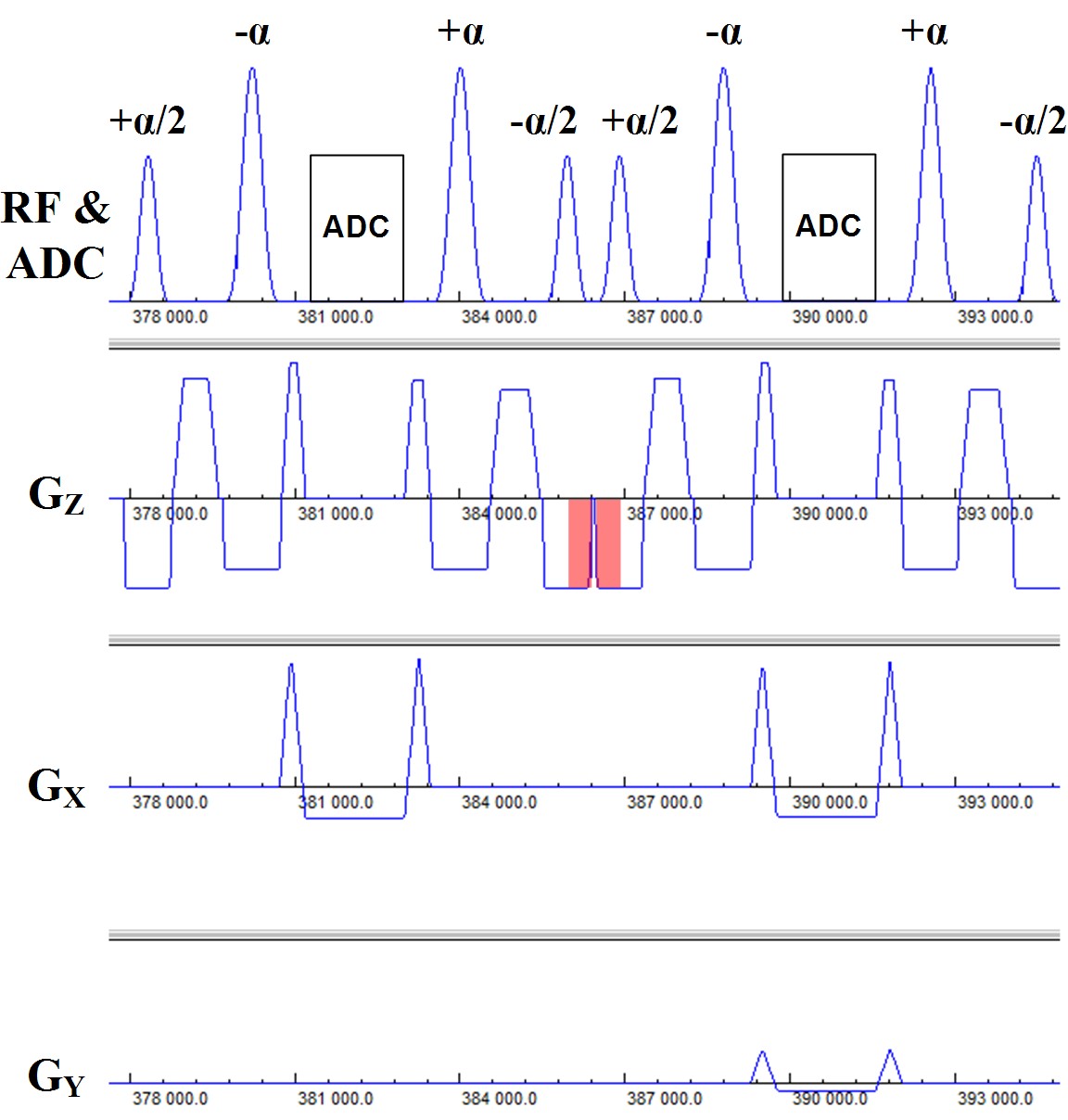
The pulse sequence diagram for FISS imaging is shown in Figure 1. The FISS imaging sequence can be viewed as a mixture of TrueFISP and spoiled gradient-echo imaging in that it consists of a series of modules of the form: [+α/2,(-α,readout,+α)n,-α/2,spoil], where α denotes the radiofrequency flip angle, and n denotes the number of repetitions. Analogous to TrueFISP, the FISS technique uses balanced gradients between the ±α pulses. Akin to spoiled gradient-echo imaging, the gradient area between the trailing -α/2 pulse of the current module and leading +α/2 pulse of the next module is not balanced in the slice direction. Of note, the use of ±α/2 pulses and gradient spoiling takes cues from prior work,3,4 but differs in that the FISS technique interrupts the TrueFISP echo train to an extreme degree.
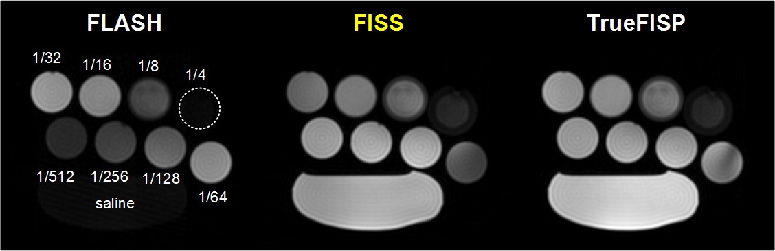
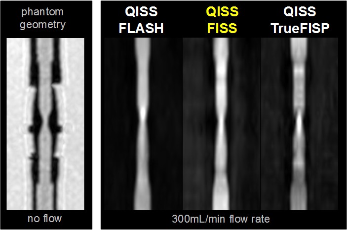
The MRI signal properties of FISS were examined using numerical simulations and phantom studies. Phantom studies involved imaging various dilutions of gadopentetate dimeglumine (Bayer, Berlin) to evaluate image contrast, as well as a pulsatile flow loop (tubing inner/stenotic diameter of 6.4/3.2mm, 300mL/min flow rate) to examine flow-related artifact. Preliminary in vivo studies tested a FISS implementation of quiescent-interval slice-selective (QISS) magnetic resonance angiography in the carotid arteries.5 All imaging was done on a 3T system (MAGNETOM Skyra Fit, Siemens, Erlangen, Germany) using radial k-space sampling. Typical FISS imaging parameters were as follows: 1.0mm in-plane spatial resolution, 320-384 matrix, flip angle (α) of 30-90°, 96-300 radial views, 3mm slice thickness, -α to +α spacing of 3.6-3.9ms, FISS module repetition time ≈8ms, n=1, 1-3 shots per slice. Comparisons were made with respect to TrueFISP and FLASH using comparable imaging parameters.
Results
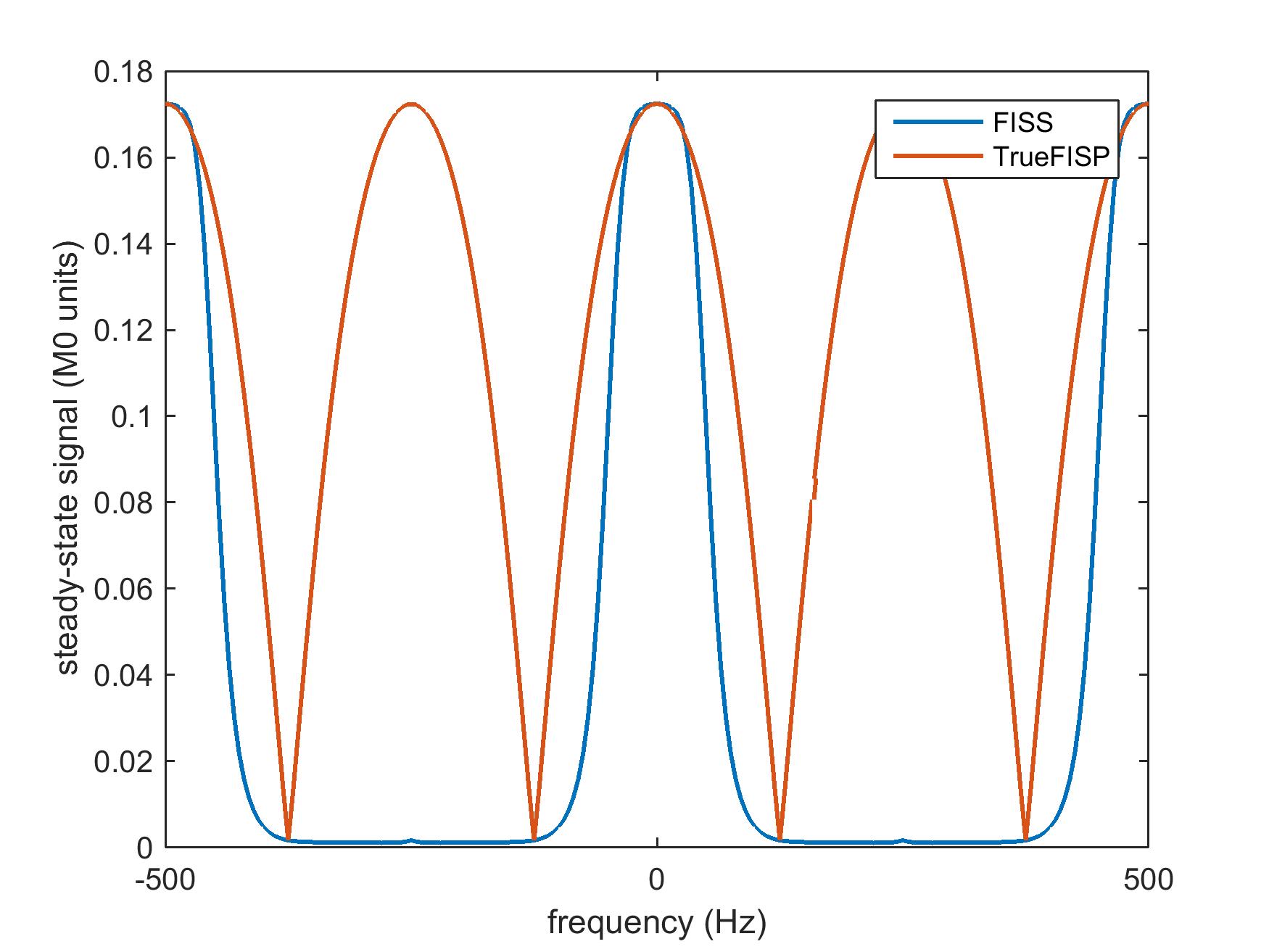
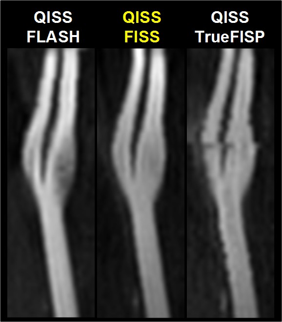
The simulated steady-state transverse magnetization of FISS as a function of off-resonance frequency is shown in Figure 2. With respect to TrueFISP, FISS provides: a) a narrower passband for imaging on-resonant spins; b) suppression of adjacent bands of off-resonant spins; and c) a MRI signal similar to TrueFISP for imaging on-resonant spins. Phantom studies showed that FISS provides a contrast that resembles TrueFISP (Figure 3), but with reduced flow-related artifact (Figure 4). In imaging of the carotid arteries, QISS FISS magnetic resonance angiography provided more uniform arterial signal than QISS TrueFISP, without the signal saturation artifact observed with QISS FLASH (Figure 5).Discussion and Conclusion
Fast interrupted steady-state (FISS) provides a set of MRI signal characteristics that is distinct from TrueFISP and FLASH. The merits of FISS include inherent suppression of off-resonant spins as well as reduced flow artifact with respect to TrueFISP, while at the same time retaining the high signal efficiency of TrueFISP. Future work will entail optimizing the FISS imaging technique and applying it throughout the body.Acknowledgements
Study was funded by NIH grants R01 HL130093 and R21 HL126015.References
1. Haase A, Frahm J, Matthaei D, Hanicke W, Merboldt KD. FLASH imaging. Rapid NMR imaging using low flip-angle pulses. Journal of Magnetic Resonance (1969). 1986 Apr 1;67(2):258-66.
2. Carr HY. Steady-state free precession in nuclear magnetic resonance. Physical Review. 1958 Dec 1;112(5):1693.
3. Scheffler K, Heid O, Hennig J. Magnetization preparation during the steady state: Fat-saturated 3D TrueFISP. Magnetic resonance in medicine. 2001 Jun 1;45(6):1075-80.
4. Derbyshire JA, Herzka DA, McVeigh ER. S5FP: Spectrally selective suppression with steady state free precession. Magnetic resonance in medicine. 2005 Oct 1;54(4):918-28.
5. Edelman RR, Sheehan JJ, Dunkle E, Schindler N, Carr J, Koktzoglou I. Quiescent-interval single-shot unenhanced magnetic resonance angiography of peripheral vascular disease: Technical considerations and clinical feasibility. Magn Reson Med. 2010 Apr;63(4):951-8.
Figures