3955
Root-flipped multiband pulses with inherently aligned echoes1Division of Imaging Sciences and Biomedical Engineering, King's College London, London, United Kingdom
Synopsis
Root-flipped multiband pulses have peculiar spin-echo behaviour due to their non-linear phase profile. In spin-echo sequences, different slices will typically have different relaxation weightings. This work investigates the typical time-delays of the spin-echoes such pulses, and proposes a novel root-flipping method to minimize differences in relaxation weighting.
Purpose
Root-flipping is a recently proposed method for designing multiband band refocusing pulses (1). It produces shorter pulses than the phase-optimized (2) and time-shifted (3) methods because RF energy is more evenly distributed across the duration of the pulse. Consequently, the spin-echo formation in different slices develops differently. The two quantities of interest are the echo arrival time ($$$T_{arr}$$$) for each slice, and the time that magnetization in each slice spends in the transverse plane ($$$T_{xy}$$$) (see Figure 1). For a conventional sequence these terms are equal to the echo time, but this is not the case for root-flipped designs. Here we use $$$\Delta$$$$$$T_{xy}$$$ and $$$\Delta$$$$$$T_{arr}$$$ to describe the largest spread in these parameters across the multiple slices. Previous work (3,1) has identified three terms to classify this effect:
1) Aligned-echo excitation: Matching the bandwidth of the excitation pulse to that of the refocusing pulse. Echoes arrive simultaneously but with different $$$T_{2}$$$-weighting. At readout, $$$\Delta$$$$$$T_{arr}=0$$$ and $$$\Delta$$$$$$T_{xy}\neq0$$$.
2) Align-TE excitation: Matching the duration of the excitation pulse to that of the refocusing pulse. Echoes arrive at different times with equal $$$T_2$$$-weighting. At readout, $$$\Delta$$$$$$T_{arr}\neq 0$$$ and $$$\Delta$$$$$$T_{xy}=0$$$
3) Minimum-duration excitation: Matching the peak-amplitude of the excitation pulse to that of the refocusing pulse. Echoes arrive at different times with different $$$T_2$$$-weighting. At readout, $$$\Delta$$$$$$T_{arr}\neq0$$$ and $$$\Delta$$$$$$T_{xy}\neq0$$$.
In this work, we propose a novel root-flipping algorithm that aligns the echoes such that $$$\Delta$$$$$$T_{arr}\approx0$$$ and $$$\Delta$$$$$$T_{xy}\approx0$$$.
Theory
In the root-flipping method the multi-slice frequency profile is represented as roots along the unit circle on the complex plane. The stopband frequencies have roots on the unit circle and the passband frequencies have roots away from this. Flipping roots inside or outside the unit circle redistributes the pulse energy in the time-domain. In the original method from Sharma et al. (1), the root-pattern across each passband was unconstrained. Having an unequal number of roots inside and outside the unit circle across a passband leads to temporal displacement, which leads to a difference in spin-echo development for different slices.
Ensuring an equal number of roots inside and outside the unit circle for each passband restricts temporal displacement, which results in $$$\Delta$$$$$$T_{arr}\approx0$$$ regardless of the excitation method. This arrangement approximates the root pattern from a linear-phase design typically found with phase-optimized pulses (2). Using this in conjunction with the “align-TE” excitation method also gives the desired property, $$$\Delta$$$$$$T_{xy}\approx0$$$. We refer to this as the “align-all” approach.
Methods
The proposed root-flip pattern requires pulses with an even number of passband roots. This is related to the time-bandwidth product (TBP) of the target design. For example, TBP=4 gives two roots per passband; all pulses in this work were designed this way. The root-flipping method searches through root-flipping patterns to obtain the solution with the lowest RF peak-amplitude. The Genetic Algorithm in Matlab was used to perform this search. The original flipping pattern was used (code made available by Sharma et al. http://www.vuiis.vanderbilt.edu/~grissowa/) alongside a modified version which selects an even number of roots per passband closest to the passband-center and flips them evenly across the unit circle (Figure 2).
The signal evolution for transverse magnetization in the presence of dephasing was simulated using Bloch simulations with a secondary frequency axis. The predicted signal was estimated by Lorentzian weighted-averaging along this axis for $$$T_{2}^{*}$$$=45ms and $$$T_{2}$$$=80ms, which correspond to human white matter values at 3T (4). The nominal echo time of this sequence was 90ms.
Results
Figure 3 shows a multiband-5 example spin-echo simulation. As expected, either $$$T_{arr}$$$ or $$$T_{xy}$$$ differs through the group of five simultaneously excited slices for the existing methods. The proposed approach results in nearly complete alignment of the echoes. Figure 4 shows that the result is stable across a range of designs. Figure 5 shows that on average the align-all root-flipped pulses are 19.6% longer in duration than those from the original method. This is expected, since they are more constrained designs.
Discussion and Conclusion
Root-flipping for reducing the peak amplitude of RF refocusing pulses results in a spread of echo arrival time ($$$\Delta$$$$$$T_{arr}$$$) and/or ‘transverse time’ ($$$\Delta$$$$$$T_{xy}$$$) of the magnetization in different slices, leading to different $$$T_{2}^{*}$$$ and/or $$$T_2$$$-weighting. We propose a constrained root-flipping approach that minimises both issues, which comes at a cost in slightly increased pulse duration (19.6%). A limitation is that the approach requires an even number of roots per passband, constraining the choice in time-bandwidth product. It was empirically found that TBP designs between 3.40 and 4.2 lead to two roots per passband, but an analytic relationship has not been identified.Acknowledgements
This work is funded by the King’s College London & Imperial College London EPSRC Centre for Doctoral Training in Medical Imaging (EP/L015226/1) and by MRC strategic grant (MR/K0006355/1). SJM acknowledges support from the EPSRC (EP/L00531X/1). Publically available code for root-flipped pulses from Sharma et al. was downloaded from http://www.vuiis.vanderbilt.edu/~grissowa/.References
1. Sharma A, Lustig M, Grissom WA. Root-flipped multiband refocusing pulses. Magn. Reson. Med. 2016;75:227–237. doi: 10.1002/mrm.25629.
2. Wong E. Optimized phase schedules for minimizing peak RF power in simultaneous multi-slice RF excitation pulses. Proc. Intl. Soc. Mag. Reson. Med. 20 2012;20:2209.
3. Auerbach EJ, Xu J, Yacoub E, Moeller S, Ugurbil K. Multiband accelerated spin-echo echo planar imaging with reduced peak RF power using time-shifted RF pulses. Magn. Reson. Med. 2013;69:1261–7. doi: 10.1002/mrm.24719.
4. Wansapura JP, Holland SK, Dunn RS, Ball WS. NMR relaxation times in the human brain at 3.0 Tesla. J. Magn. Reson. Imaging 1999;9:531–538. doi: 10.1002/(SICI)1522-2586(199904)9:4<531::AID-JMRI4>3.0.CO;2-L.
Figures
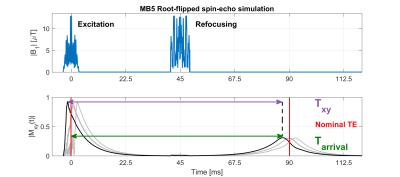
Figure 1:
Top: RF excitation and refocusing pulses (root-flipped design with 5 slices) for a nominal TE of 90ms.
Bottom: Transverse magnetization as a function of time for the five slices. All bar one slice evolution have been faded out for clarity. $$$T_{xy}$$$ is the time from excitation to the moment the slice fully refocuses. $$$T_{arr}$$$ is the time from the center of the excitation pulse to the moment the slice fully refocuses. For conventional spin-echo sequences these two values are equal to the nominal echo-time.
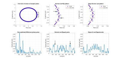
Figure 2:
Top: Root-plots on the complex plane for a normal root-flipped pulse (middle) and an align-all root-flipped pulse (right). The arrows indicate passbands with an unmatched number of roots about the unit circle which lead to temporal displacement of RF energy in the time-domain.
Bottom: RF pulses for each root-pattern. Before any flipping, RF energy is focused at the start of the pulse. Normal Root-flipped pulses optimally distribute RF energy, which usually implies temporal displacement. Align-all pulses have an even number of passband roots for all passbands and consequently excite and refocus the center of the slices almost simultaneously.
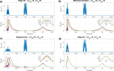
Figure 3:
Example of Spin-echo simulations for multiband 5 pulses with different excitation methods for a nominal echo time of 90ms. The five slices were simulated with $$$T_2$$$ and $$$T_{2}^{*}$$$ relaxation.
The spin-echo sequences in subfigures a), b) and c) all use the same refocusing pulse, with Align-TE, Minimum-duration and aligned-echo excitation respectively. a) and b) only differ in a small amount of $$$T_2$$$-weighting across the slices.
c) shows aligned echoes with different $$$T_2$$$-weighting.
d) shows an Align-all example, where the echoes arrive almost simultaneously with almost equal $$$T_2$$$-weighting.
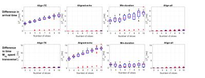
Figure 4:
Top row: Difference in echo arrival time ($$$\Delta$$$$$$T_{arr}$$$) for a range of multiband factors and slice separations. The aligned-echo has perfect time-alignment, where-as the Align-TE and minimum duration have a few milli-seconds of mismatch. This will lead to a difference in $$$T_{2}^{*}$$$-weighting. Align-all comes very close to aligning the echoes, which will happen regardless of the excitation method used.
Bottom row: Difference between the longest and shortest $$$T_{xy}$$$. This value is near zero for the Align-TE method and similar for the Align-all method. Outliers (red crosses) show that Align-all solutions can also be found without the constraint.
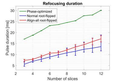
Figure 5:
Duration comparison between phase-optimized, normal root-flipped and align-all root-flipped pulses. The main trace indicates the average duration across pulses designed for an inter-slice separation of 3 to 16 slices from slice to slice center. The errorbars indicate the maximum and minimum duration found across slice separations. For refocusing pulses, the average duration increase is 19.6%. The large spread in duration for the high multiband factor could indicate that the optimal solution was not found in the optimization.