3953
Gradient Field Design for RF Excitation in Simultaneous Multi-Slice and Simultaneous Multi-Slab Imaging by Using a Z-Gradient Array1National Magnetic Resonance Research Center (UMRAM), Bilkent University, Ankara, Turkey, 2Electrical and Electronics Engineering, Bilkent University, Ankara, Turkey
Synopsis
Multiple locations inside the volume of interest can be mapped to same frequency by applying spatially oscilating magnetic fields (SOMFs) created by 9 channel z-gradient array. Such a mapping can lead to excitation of multiple slices or slabs with a single band RF pulse as well as doubling the number of slices excited by a multi-band RF pulse. Depending on the slice or slab locations, spatially oscillating magnetic fields can be shifted using a independent gradient amplifiers. We have demonstrated 2 slab excitation with a single band RF pulse and 6 slice excitation with a 3-band RF pulse.
Purpose
Simultaneous multi-slice (SMS) sequences require demanding RF pulses in terms of peak power, SAR and pulse duration1. Although there are smart techniques to overcome the RF pulse limitations1, optimized SMS-RF pulses has either longer duration or higher SAR than single slice RF pulses if the same techniques are applied to single slice RF pulses. Additionally, Multiband-Multislab technique has been recently proposed to combine the advantages of SMS with a 3D readout2. Although multislab excitation is less demanding than multislice excitation, RF pulses are always desired to be as short as possible due to B0 robustness and shorter echo times.
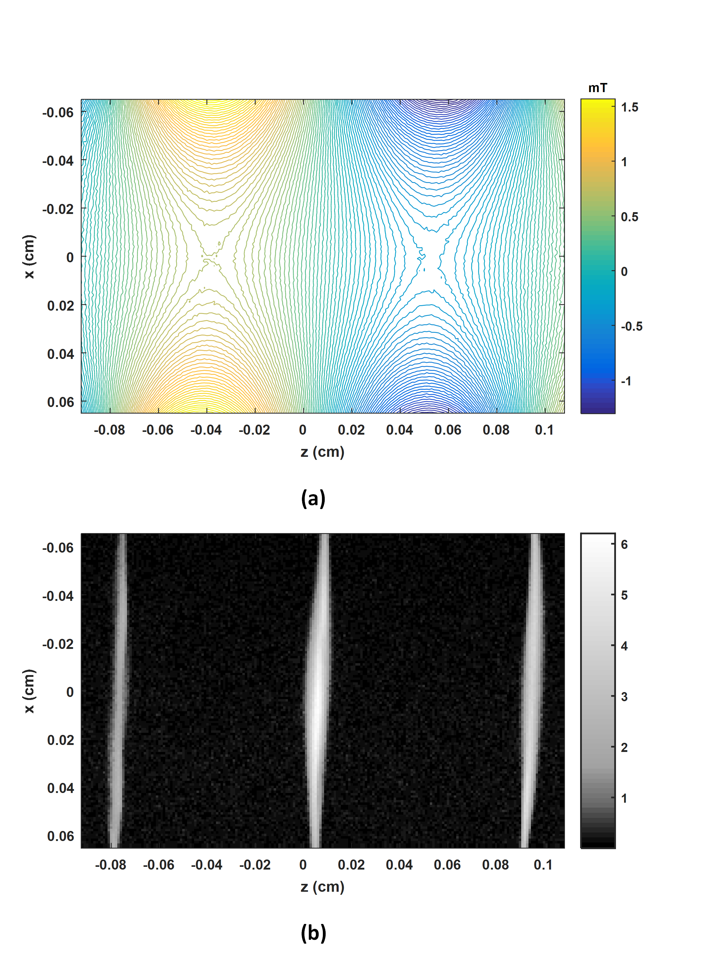
Previously, we had demonstrated that exciting multiple slices with a single band RF pulse by generating spatially oscillating magnetic fields (SOMF) with a z-gradient array is possible3. Fig.1a shows an example of SOMF. In Fig.1b, the experimental coronal image shows that 3 slices can be excited with a single band RF pulse. Magnetic field profile in Fig.1 acts as a linear gradient profile locally in the very limited volume around the slice locations. This work is aimed at creating SOMF with extended linear gradient volumes in multiple regions. It is used to excite two slabs with a single band RF pulse as well as doubling the number of slices excited with a conventional Multiband RF pulse using a z-gradient array.
Methods
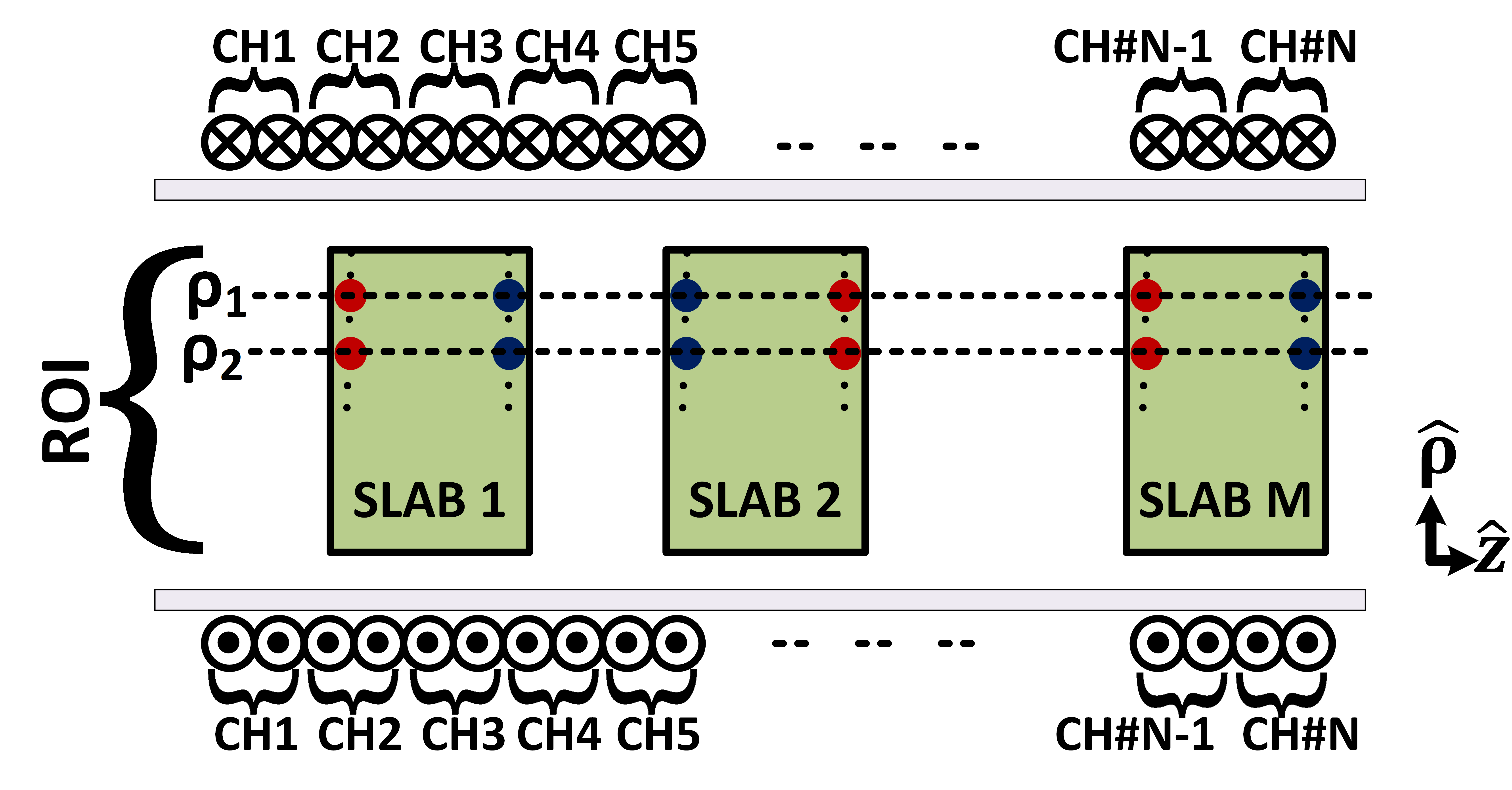
If multiple locations are encoded to the same frequency with SOMF, single frequency band of the RF pulse corresponds to multiple spatial locations. In order to generate SOMF with extended linear gradient regions, current weightings have to be optimized for each channel. As explained in Fig.2, two sets of design points have to be determined, and designing magnetic fields at only design points can produce linear gradients in the slab volume. Magnetic field of design points at each set should be equal. If two design points in the constant z plane are close enough, their first radial derivative vanishes. Due to zero Laplacian assumption of low frequency magnetic fields and angular symmetry of the coil, second z derivative also vanishes. After maximizing field difference between the two sets, linear gradient distribution is the only field distribution satisfying zero second derivative. Method requires at least 4M-2 channels where M is the number of slabs. Additional channels can be utilized to maximize the gradient strength and minimize the power. Maximum ratings of the amplifiers considering mutual coupling between elements are constrained.
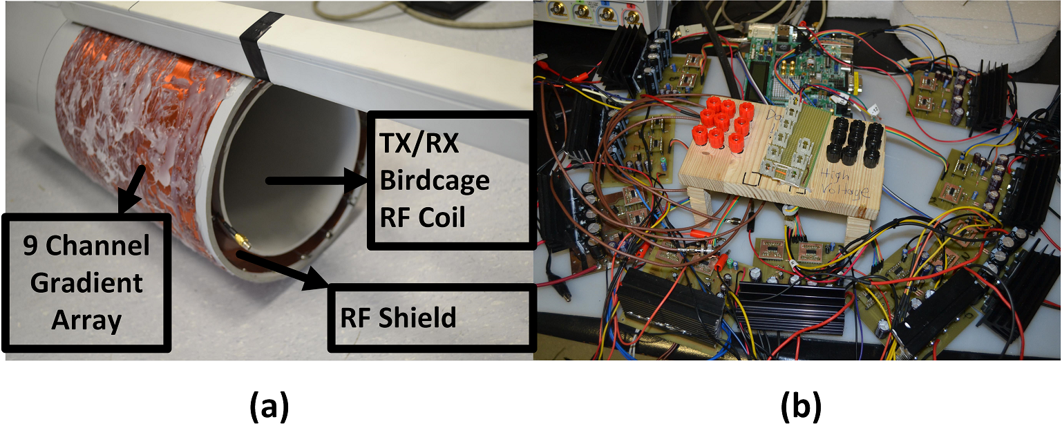
A nine-channel gradient array with a diameter of 25cm and total length of 27.5cm is used to generate such SOMFs. The array is driven dynamically using inexpensive, custom made 50V-20A independent gradient amplifiers. Fig.3 shows the image of the hardware components in the experiments.
Results
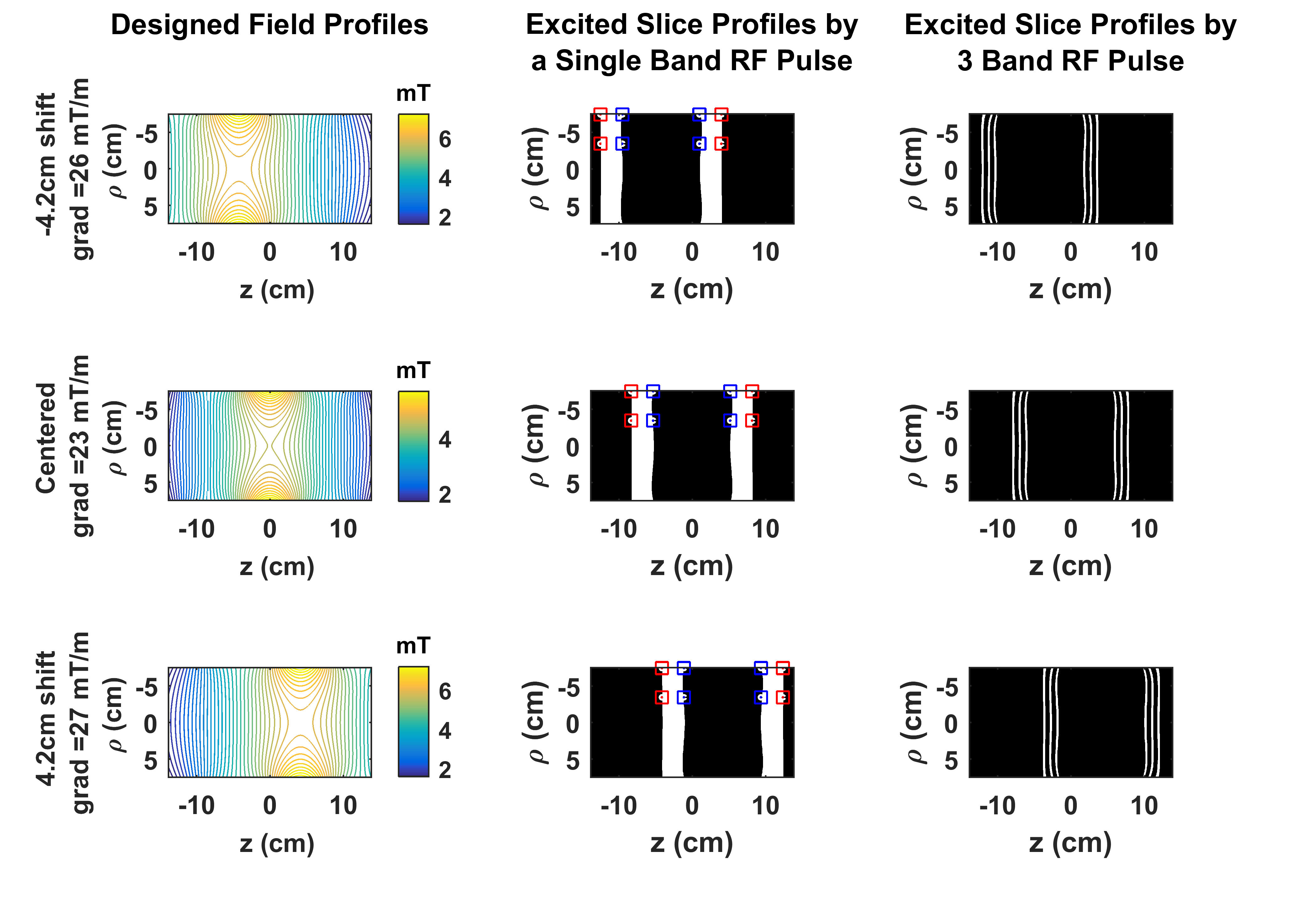
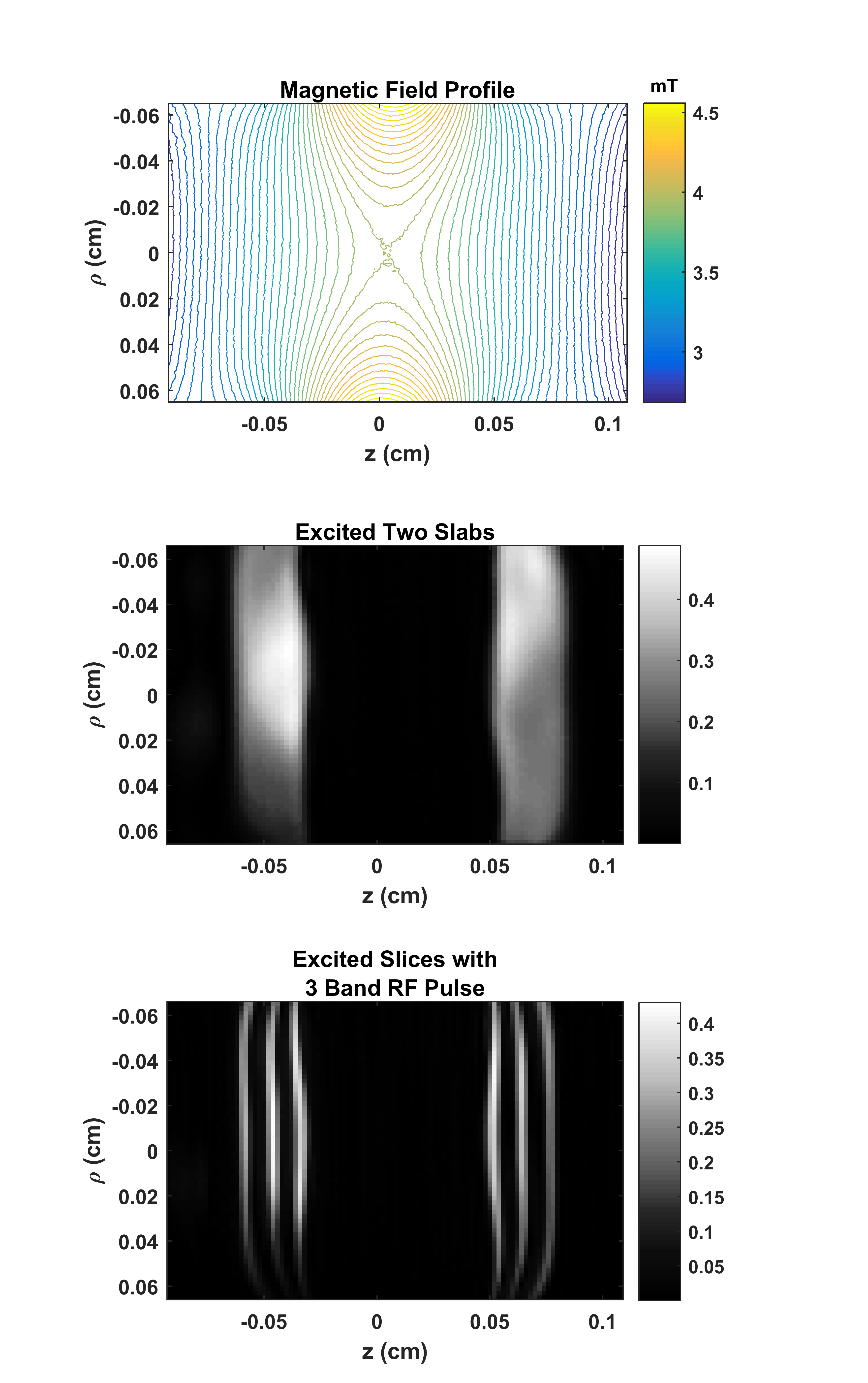
The first column of Fig.4 shows the simulations of the designed SOMFs for each shifted case. Second column indicates the design points on top of the excited slab profiles with a single band RF pulse. Third column in Fig.4 shows the slice profiles excited with superposition of 3 RF pulse with different frequencies, i.e. multi-band RF pulse. Maximum attainable gradients and RMSE of the slab thickness are around 25 mT/m and 5%, respectively.
Fig.5a is the expected magnetic field distribution obtained with measured field profiles. Fig.5b shows the coronal image of a phantom to demonstrate the slab excitation with a single-band Hamming-windowed sinc pulse. Figure 5c shows 6 slices excited with a superposition of 3 RF pulses with different frequencies.
Discussion
Although there is a slight curvature in slab profiles, it can be handled in the 3D readout strategy with additional partition encodings. When multi-band pulses are used, excited slices are not evenly distributed in the whole volume, but are rather close to each other. Such a disadvantage due to receive coil sensitivities can be handled with Blipped-CAIPI4 to differentiate the transverse images.
The proposed method is only demonstrated for excitation pulses; however, this method applies to conventional refocusing or inversion pulses without any modification to the original pulse. The attainable gradient strength is dependent on the imaging volume, number of channels, length and radius of the coil elements. Gradient array can also produce linear z-gradient for the readout part.
Future work includes the design of slightly larger shielded coils including transverse coils for human brain imaging and RF receive array to be implemented in SMS and multi-slab imaging.
Conclusion
Excitation of multiple slabs with a single band RF pulse and doubling the number of excited slices with multiband RF pulse are shown to be feasible in simulations and experiments by using a z-gradient array.Acknowledgements
No acknowledgement found.References
1. Barth, Markus, et al. "Simultaneous multislice (SMS) imaging techniques."Magnetic resonance in medicine 75.1 (2016): 63-81.
2. Schulz, Jenni, Rasim Boyacioglu, and David G. Norris. "Multiband multislab 3D time-of-flight magnetic resonance angiography for reduced acquisition time and improved sensitivity." Magnetic resonance in medicine (2015).
3. K. Ertan, S.Taraghinia, A. Sadeghi, E. Atalar “A z-gradient array for spatially oscillating magnetic fields in multi-slice excitation” Magn Reson Mater Phy (2016) 29: 1. doi:10.1007/s10334-016-0568-x, Abstract No:81.
4. Setsompop, Kawin, et al. "Blipped-controlled aliasing in parallel imaging for simultaneous multislice echo planar imaging with reduced g-factor penalty." Magnetic Resonance in Medicine 67.5 (2012): 1210-1224.
Figures