3952
Using Pre-calculated Direct Signal Control Solutions for 7T 3D FLAIR Brain Imaging1Biomedical Engineering and imaging Sciences, King's College London, London, United Kingdom, 2Image Sciences Institute, University Medical Centre Utrecht, Utrecht, Netherlands, 3Centre for the Developing Brain, King's College London, London, United Kingdom
Synopsis
Direct Signal Control can be used for improving signal uniformity for TSE based 3D-FLAIR imaging at 7T by using dynamic RF shimming through the echo train. The need to calibrate and optimize on a subject-specific basis can be a workflow issue. In this work we evaluate generic solutions that are calculated in advance, in comparison with individual subject-specific optimizations.
Purpose
The Direct Signal Control (DSC) framework1 can be used to optimise signal in fast spin echo sequences, improving image homogeneity and contrast. DSC involves applying radio-frequency (RF) shims on a pulse-by-pulse basis and changing them dynamically in order to optimise signal properties. By optimizing with a spatially-resolved extended phase graph (SR-EPG) model2, much greater control of the MRI signal throughout the echo train is afforded.
DSC does however require in-situ calibration (B$$$_1^+$$$ mapping) and on-line optimisation, which is less desirable for workflow in a clinical exam.
In this work the potential to forego a subject-specific DSC optimisation in lieu of pre-calculated DSC solutions was compared with the subject-specific optimisation and quadrature mode. This was explored for 3D fluid attenuated inversion recovery (FLAIR) brain imaging at 7T3.
Methods
All data was acquired on a Philips 7T MRI system using an 8 transmit channel head coil with 32 receive channels (Nova Medical, Wilmington, DE). B$$$_1^+$$$ maps were acquired using DREAM4 in quadrature mode from a “training” set of 5 subjects. Together with a series of per-channel low flip-angle gradient echo images, these were used to generate per-channel B$$$_1^+$$$ maps.
The B$$$_1^+$$$ maps were used to compute three pre-calculated DSC solutions:
1. Complex mean of the individual solutions - “Mean Solution”
2. A single large DSC calculation where B$$$_1^+$$$ maps from all the subjects were concatenated and used in a single large optimization similar to the universal PTx pulse design method5 - “Universal Solution”
3. A DSC solution computed from B$$$_1^+$$$ maps from an electromagnetic field simulation of the head coil used in this work - “Simulation Solution”
Imaging, calibration and individual DSC design was performed on five further subjects who were not part of the training group. The 3D-FLAIR sequence used was based on Reference 3 with 1 mm isotropic resolution, FOV 250x250x190mm, repetition time 8s and inversion time 2250ms. The sequence incorporates a T2 prep phase prior to the inversion pulse and the imaging sequence in order to improve T2 weighting.
The refocusing pulses in the echo train (comprised of 192 echoes) had flip angles which quickly swept down to 50º and the DSC calculation was optimised for this sweep using the methodology from Reference 6. To ensure a reasonable online computation time, 16 RF shims were used - the first 13 shims were applied to the first 13 pulses and the three remaining shims were applied to groups of 60 pulses.
In the optimisation, the echoes were weighted with a linear ramp such that the first and last echoes had a weighting of zero and the central k-space echo maximum weighting.
Imaging was performed for the FLAIR sequence in quadrature mode, optimised for the individual, and with the three pre-calculated solutions. Strict power constraints of 1W forward power measured at the coil connection plane were adhered to for safety – all the DSC results had lower power compared with quadrature mode.
Results
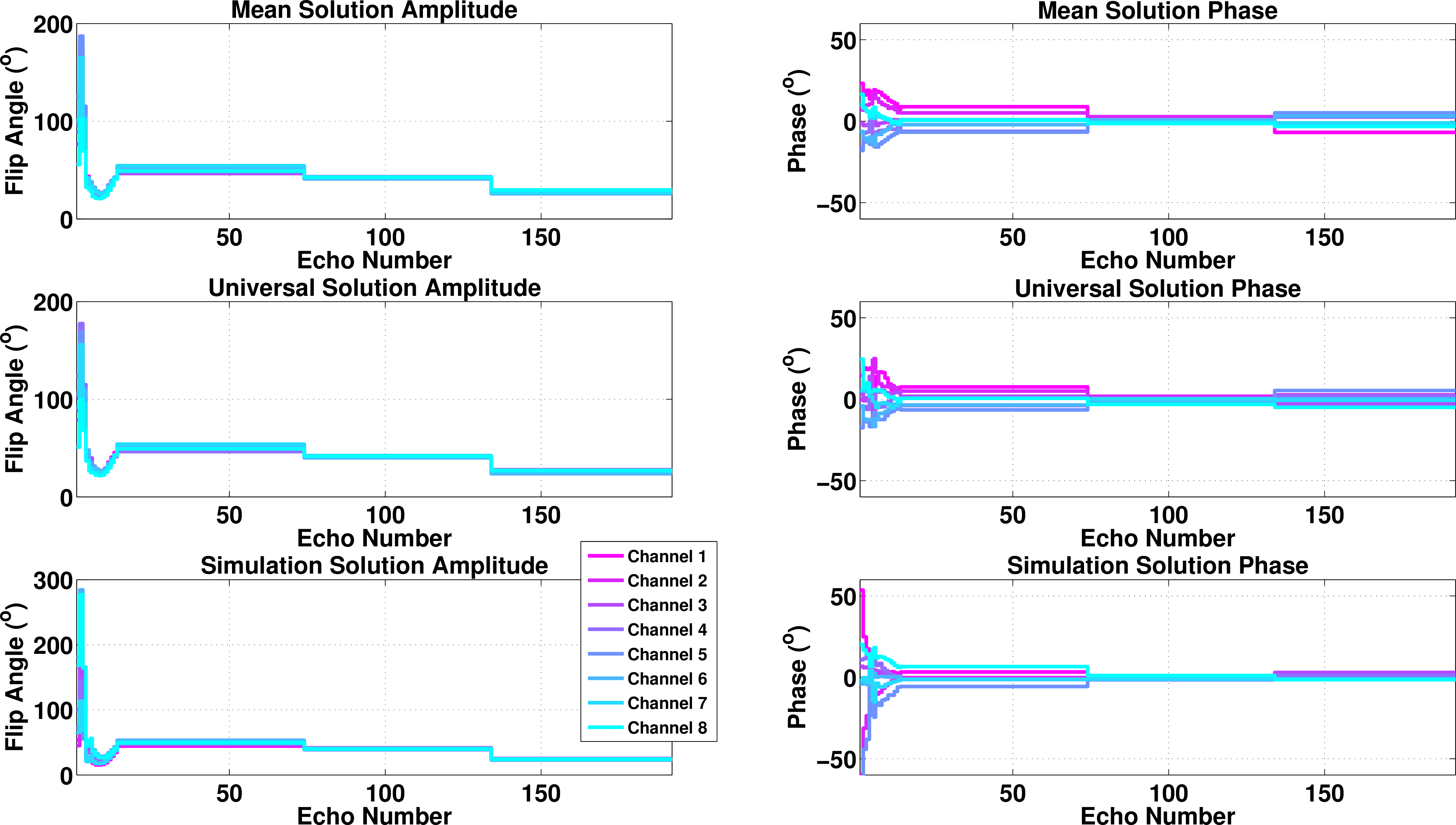
Figure 1 shows the flip angle amplitudes and phases of the pre-calculated solutions. The correlation coefficient between the (complex) mean and universal solutions is 0.98 indicating very strong correlation. This reduces to ~0.69 when compared with the solution computed from simulation.
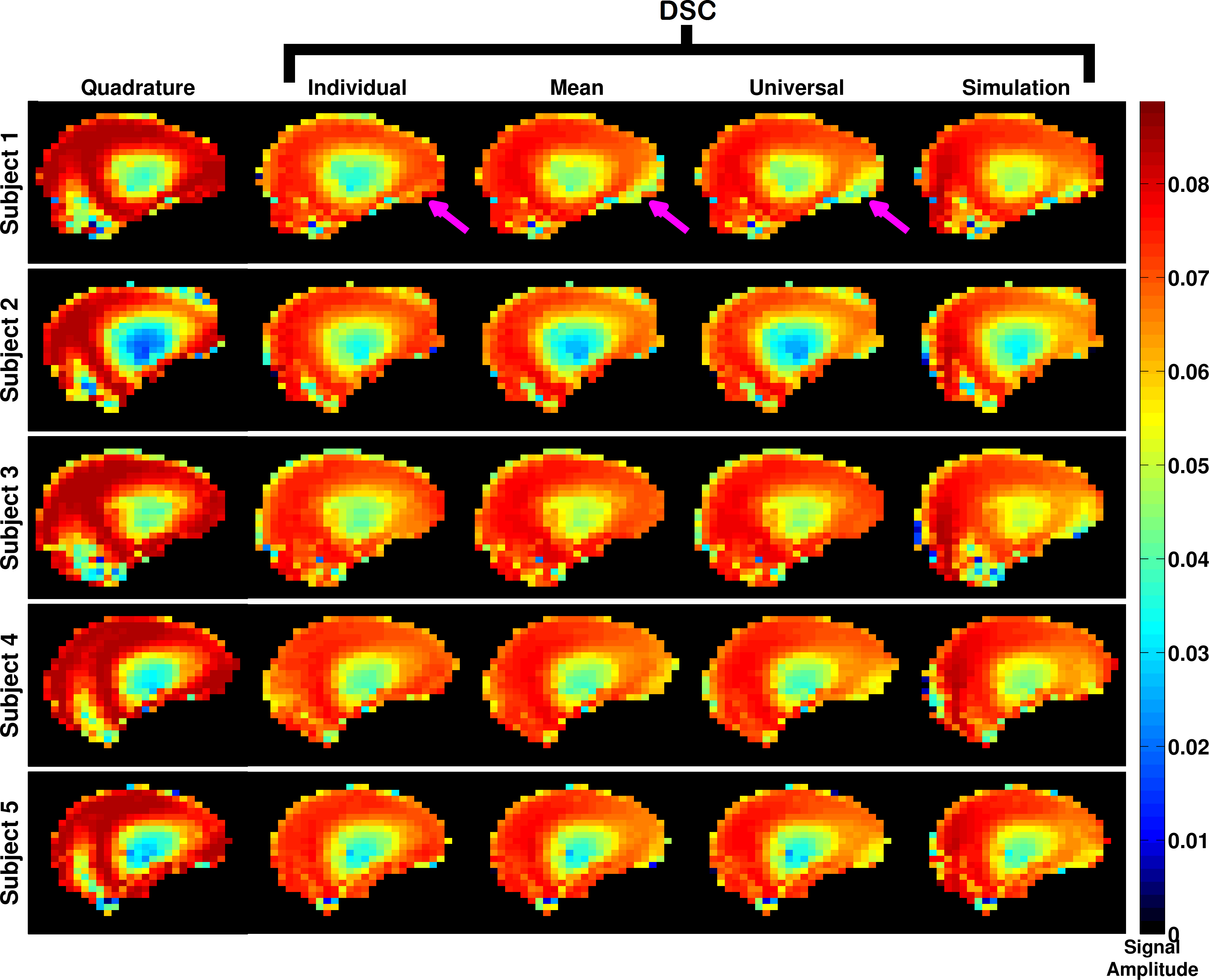
Figure 2 shows the predicted signal amplitudes from the SR-EPG model at the central k-space echo in a mid-sagittal slice for all three subjects imaged for quadrature mode, individually optimised for the given subject and for the three pre-calculated solutions. All the pre-calculated solutions improve the signal homogeneity compared with quadrature mode.
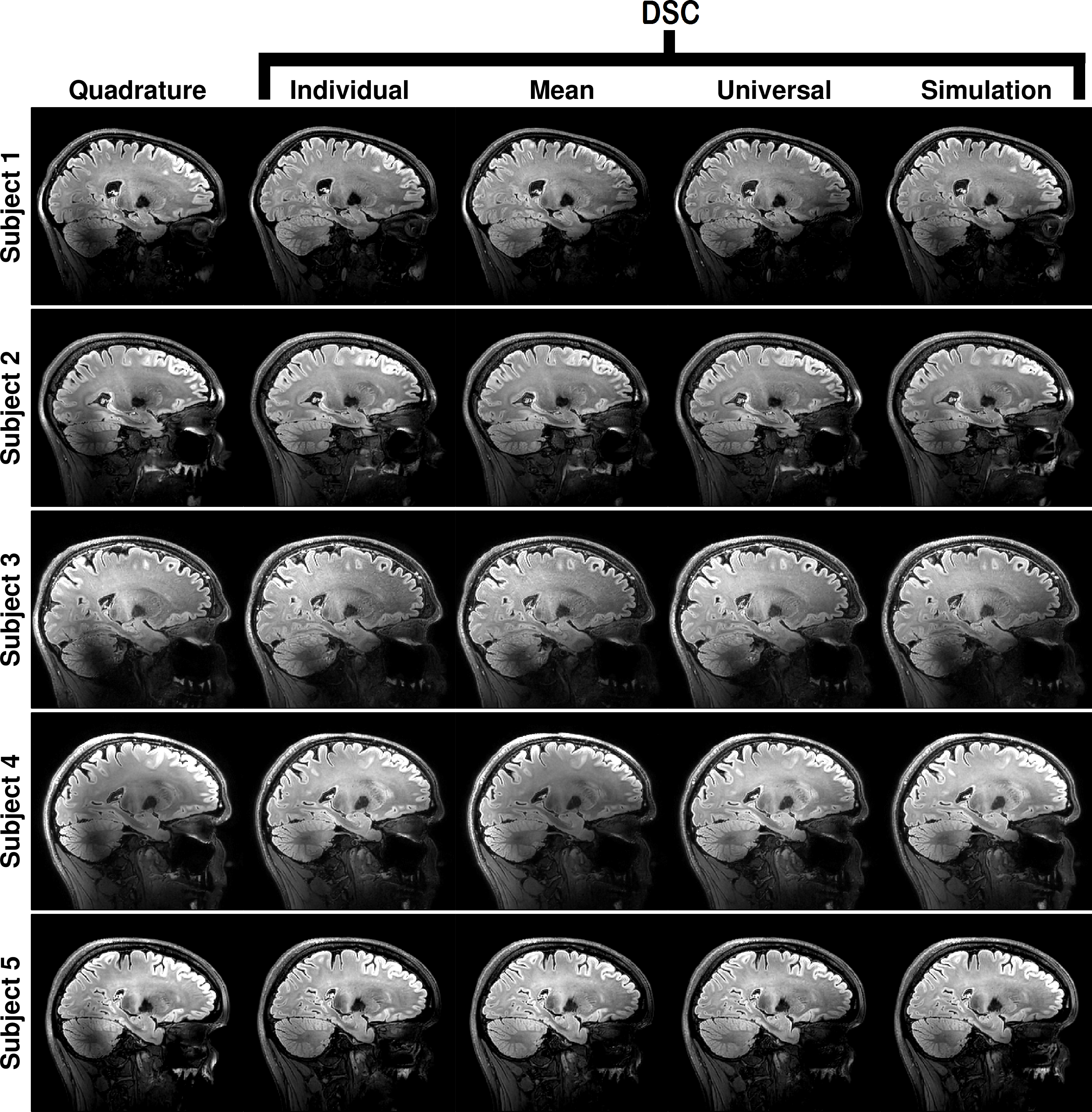
The imaging results for a sagittal view through the right-hand lobe of the cerebellum are shown in Figure 3 for all the subjects and scenarios as in Figure 2. The individually optimised solutions recover the region of low signal that is always seen in the cerebellum. The three pre-calculated solutions are also able to do this to varying degrees, however the simulation based solution performs least effectively.
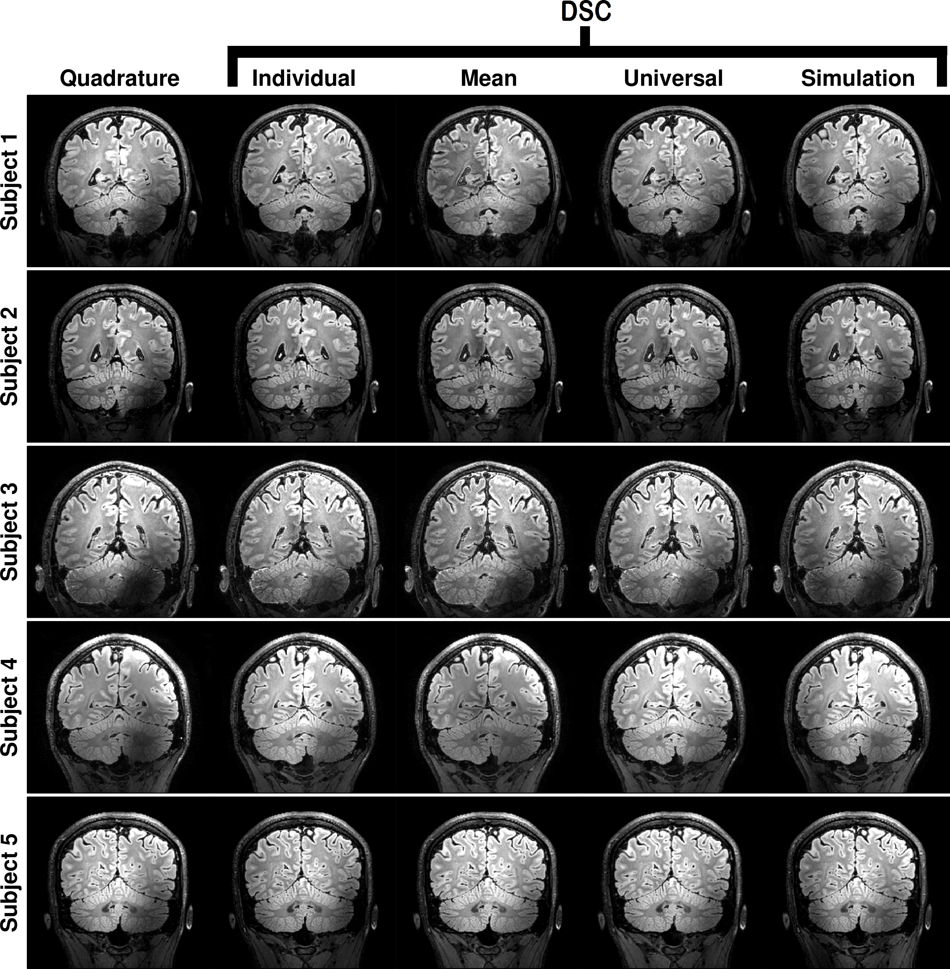
Figure 4 shows the same data but for a coronal slice through the cerebellum.
Discussion and Conclusions
The feasibility of using pre-calculated direct signal control solutions to improve signal homogeneity in a 3D FLAIR sequence at 7T was assessed. It was found that it is possible to recover regions of low signal in the cerebellum and the centre of the brain using these solutions to a comparable degree of efficacy as optimising specifically for a subject; thus potentially allowing these to be used without subject-specific, online calculations having to be performed. Further experiments with a wider range of subjects are needed to assess robustness of the generic solutions.Acknowledgements
The research was funded by the following grant:
EPSRC (UK research councils) grant number EP/L00531X/1
References
1. Malik SJ, Beqiri A, Padormo F, Hajnal JV. Direct Signal Control of the steady-state response of 3D-FSE sequences. Magnetic Resonance in Medicine, 2015;73(3):951–963.
2. Malik SJ, Padormo F, Price AN, Hajnal JV. Spatially resolved extended phase graphs: Modeling and design of multipulse sequences with parallel transmission. Magnetic Resonance in Medicine, 2012;68(5):1481–1494.
3. Visser F, Zwanenburg JJM, Hoogduin JM, Luijten PR. High-resolution magnetization-prepared 3D-FLAIR imaging at 7.0 Tesla. Magnetic Resonance in Medicine, 2010;64(1):194–202.
4. Nehrke K, Bornert P. DREAM-a novel approach for robust, ultrafast, multislice B1 mapping. Magn. Reson. Med. 2012;68:1517–1526.
5. Gras V, Vignaud A, Amadon A, Bihan DL, Boulant N, Universal pulses: A new concept for calibration-free parallel transmission. Magn. Reson. Med.,2016; 0: pp. 1–9.
6. Sbrizzi A, Hoogduin H, Hajnal JV, van den Berg CAT, Luijten PR, Malik SJ. Optimal control design of turbo spin-echo sequences with applications to parallel-transmit systems. Magnetic Resonance in Medicine 2016.
Figures