3930
A Novel Position and Orientation Sensor for MRI1Sir Peter Mansfield Imaging Centre, University of Nottingham, Nottingham, United Kingdom
Synopsis
The effect of head motion is a significant problem for MRI. Here we present the early stages in the development of a novel device which is able to measure head pose within the scanner. By using a combination of a commercially available 3-axis MEMS accelerometer and an anisotropic magnetoresitive bridge sensor, the orientation of the device is monitored with root-mean-square accuracy of ±0.12° while translation is estimated using voltages induced in a single coil by time-varying magnetic field gradients with an accuracy of ±0.45mm. With further development, this device could be used effectively for prospective and retrospective motion correction.
Purpose
To accurately monitor position and orientation within an MRI scanner using a novel, custom-made device.Introduction
Subject motion can significantly limit the data quality achievable with MRI. Therefore there is a growing need for accurate and precise monitoring of head pose in order to correct for subject motion. Existing monitoring techniques, such as navigators [1] and optical tracking [2] have disadvantages; navigators increase scan time and cannot monitor position continuously, and optical tracking requires line-of-sight access. Recently, accelerometers [3] and inductive coils [4] have been explored for monitoring motion however the use of each of these techniques on its own is not sufficient to fully characterise head pose. Using a combination of different sensors, we therefore created a new device that can continuously monitor absolute position and orientation within the scanner without the need for line-of-sight. We evaluated the accuracy of this device at known static poses.Methods
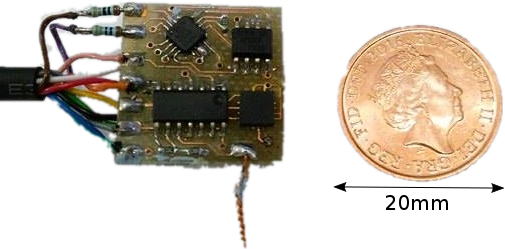
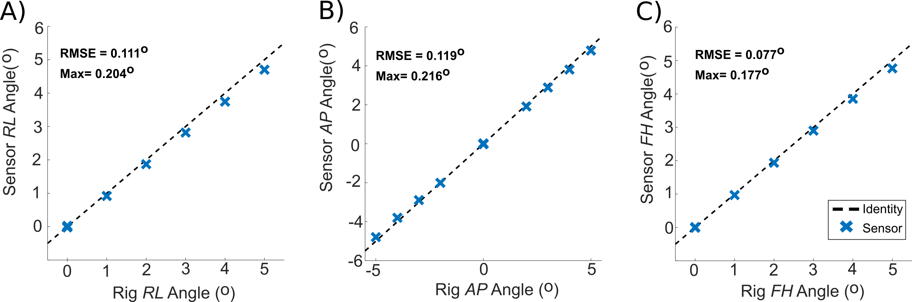
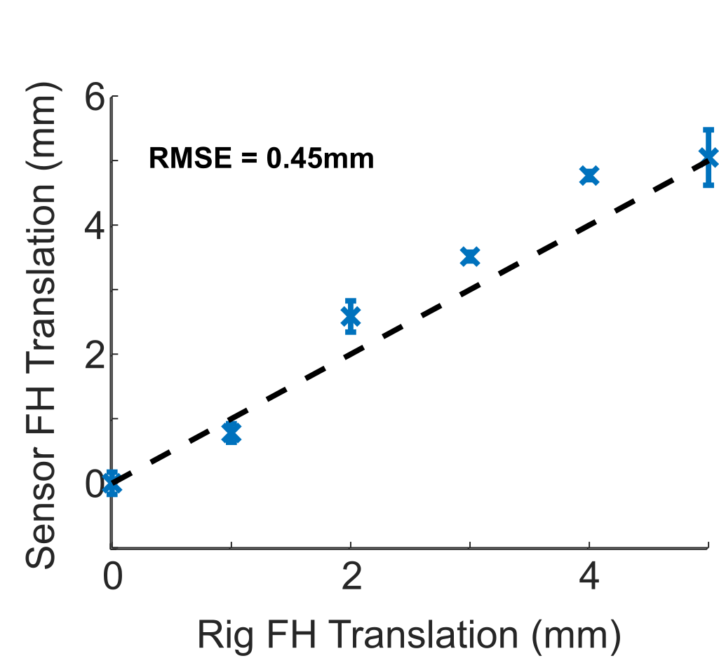
Orientation of the sensor (Fig. 1) about the foot-head (FH) and right-left (RL) directions is measured by a 3-axis analogue MEMS accelerometer, while orientation about the anterior-posterior (AP) direction is measured using an anisotropic magnetoresistive bridge sensor (AMR). The AMR consists of two Wheatstone bridges containing magnetoresistive materials which provide a quadrature measurement of angle up to 180° when saturated in the static magnetic field of the scanner. The position of the sensor is estimated by measuring the voltages induced in a single well-defined coil (14mm diameter, 50 turns) by known time-varying magnetic field gradients. The sensor was mounted on a rig capable of controlled rotations and translations (precisions of ±0.1° and ±0.1mm respectively) and placed inside the bore of a 3T Acheiva scanner (Philips, Netherlands) such that the AMR was oriented in a plane parallel to the B0-field. The sensor was then rotated in steps of 1° about the RL and FH directions up to 5° and ±5° about the AP direction. Recordings were made over 5 second in each pose using a sample rate of 100Hz and the mean signals from the accelerometer and AMR were then used to determine the orientation of the sensor. The pick-up coil was aligned such that it was parallel to the FH direction of the scanner and was translated by up to 5mm in 1mm steps along the FH direction. At each pose a custom sequence of gradient pulses [5] was applied and the voltages induced in the coil were measured. The sequence consisted of 15 repetitions of a trapezoidal gradient applied along the FH direction. Each pulse ramped-up/down over 0.2ms at a rate of 150 Tm-1s-1. The induced signals were sampled at a rate of 50kHz. Because the dimensions and orientation of the coil and gradient field are well defined, it is possible to calculate the exact position of the coil from the induced voltages. Change in positions were estimated for each direction and compared to the actual translations of the rig.Results and Discussion
The angles estimated by the sensor were compared against the true angle set by the rig (Fig. 2). The root-mean-square (RMS) difference between the estimated and true angles was calculated to be no greater than 0.12°. The error in all 3 planes of rotation increases linearly with angle, which suggests that the axes of the sensor were not perfectly aligned with the axes of the rig. Improving/compensating for the alignment should improve the precision of the orientation measurements. Moreover, the wide-band frequency response of the rotation sensors is far in excess of typical frequencies of movement. There is no evidence that vibration or natural movements from the scanner or subject will affect the measurements at low frequencies. Early experimental work also demonstrated that the MEMS and AMR sensors worked just as well at 7T. The position of the device along the FH direction estimated by the sensor is compared to the rig position in Fig. 3 with an RMS error of 0.45mm. Because the dimensions of the coil are known and the gradient fields are well characterised, it is theoretically possible to correct the position estimates when the coil is tilted off the FH axis. Moreover, with modifications to the approach it should be possible to measure absolute position in any direction. In this proof-of-principle experiment, the sampling and filtering is sub-optimal and the coil has not been optimised. With further work, it should be possible to significantly improve the accuracy of the device.Acknowledgements
The authors would like to acknowledge the work of Andrew Stuart (Electronics Workshop, School of Physics and Astronomy) in the construction of the sensor
This work was supported by funding from the Engineering and Physical Sciences Research Council (EPSRC) and Medical Research Council (MRC) [grant number EP/L016052/1].
References
[1] T. S. Sachs, C. H. Meyer, B. S. Hu, J. Kohli, D. G. Nishimura and A. Macovski, “Real-time motion detection in spiral MRI using navigators,” Magnetic resonance in medicine, vol. 32, no. 5, pp. 639--645, 1994.
[2] M. Zaitsev, C. Dold, G. Sakas, J. Hennig and O. Speck, “Magnetic resonance imaging of freely moving objects: prospective real-time motion correction using an external optical motion tracking system,” Neuroimage, vol. 31, no. 3, pp. 1038--1050, 2006.
[3] M. Paley, N. Ismail, D. Jarvis, R. Steven and G. Paul, “Wireless Accelerometer Rotational Motion Correction for Neonatal MRI,” in BCISMRM, Leeds, 2016.
[4] E. Bhuiyan, G. Spencer, P. Glover and R. Bowtell, “Tracking Head Movement inside an MR scanner using voltages induced in coils by time varying gradients,” in ISMRM, Honolulu, 2017.
[5] K. J. Mullinger, W. X. Yan and R. Bowtell, “Reducing the gradient artefact in simultaneous EEG-fMRI by adjusting the subject's axial position,” Neuroimage, vol. 54, no. 3, pp. 1942--1950, 2011.
Figures