3925
A Three-Dimensional Spiral-In/Out Turbo-Spin-Echo Technique with Long Readout Echo Train and Concomitant Phase Compensation1Imaging Research, Barrow Neurological Institute, Phoenix, AZ, United States, 2Neuroradiology, Barrow Neurological Institute, Phoenix, AZ, United States
Synopsis
TSE is a rapid technique routinely used for T2 and FLAIR imaging. Three-Dimensional TSE with variable flip angles provides high scan efficiency, high SNR, and contiguous slice coverage. In this project we develop a 3D spiral TSE sequence employing a spiral-in/out readout for efficient acquisition but without the drawbacks associated with conventional spiral-out TSE. The variable flip angle schedule is adapted for long echo space to reduce waste in acquisition time. A concomitant phase compensation technique is incorporated to minimize the violation of the CPMG condition. Preliminary results demonstrate the feasibility of the proposed technique.
Introduction
Turbo spin echo (TSE) is routinely used in the clinic for T2 or FLAIR imaging. Three-dimensional (3D) imaging has advantages over two-dimensional method, such as high SNR, contiguous slice coverage. A variable refocusing flip angle strategy has been developed for 3D TSE to allow for a long echo train, which improves the scan efficiency1,2. Compared to Cartesian acquisition, spiral acquisition has higher acquisition efficiency. Recently renewed efforts have been made on incorporating spiral readout with 3D TSE3,4. In this work, we propose a 3D TSE technique with a long spiral-in/out readout echo train for high efficiency, enabled by an adapted variable refocusing flip angle schedule, and concomitant phase compensation for improved image quality. Preliminary results are demonstrated with FLAIR imaging.Methods
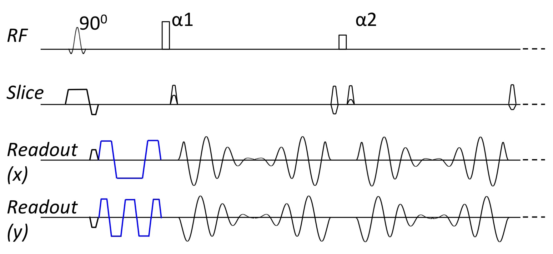
Concomitant Phase Compensation: The spiral-in/out readout was incorporated into the 3D TSE sequence to avoid off-resonance interference or degraded acquisition efficiency associated with the spiral-out readout4, as shown in Fig. 1. However, with the spiral-in/out gradient, concomitant phase accumulation causes extra phase at the spin echo, violating the CPMG condition. The reference pre-scan5 can not correct for this spatially varying phase error in 3D scan. To overcome this issue, we incorporate the quadratic nulling method6,7 to directly compensate this phase error. Extra gradients (Fig. 1, in blue color) are added between the excitation and refocusing RF pulses. These gradients approximate and thus cancel out the self-squared concomitant phase terms7 due to the spiral-in gradient. Cross-terms due to the spiral waveform are relatively small and not taken in account here. These gradients are also flow compensated. A 1-2-1 flow compensation scheme is used on one axis (x) and a 1-2-2-2-1 scheme is used on the other axis (y) to minimize the cross-terms arising from the overlapping concomitant phase compensation gradients themselves. Alternatively a simple spiral-in waveform can be used to compensate for both self-squared and cross terms but leads to longer echo space.
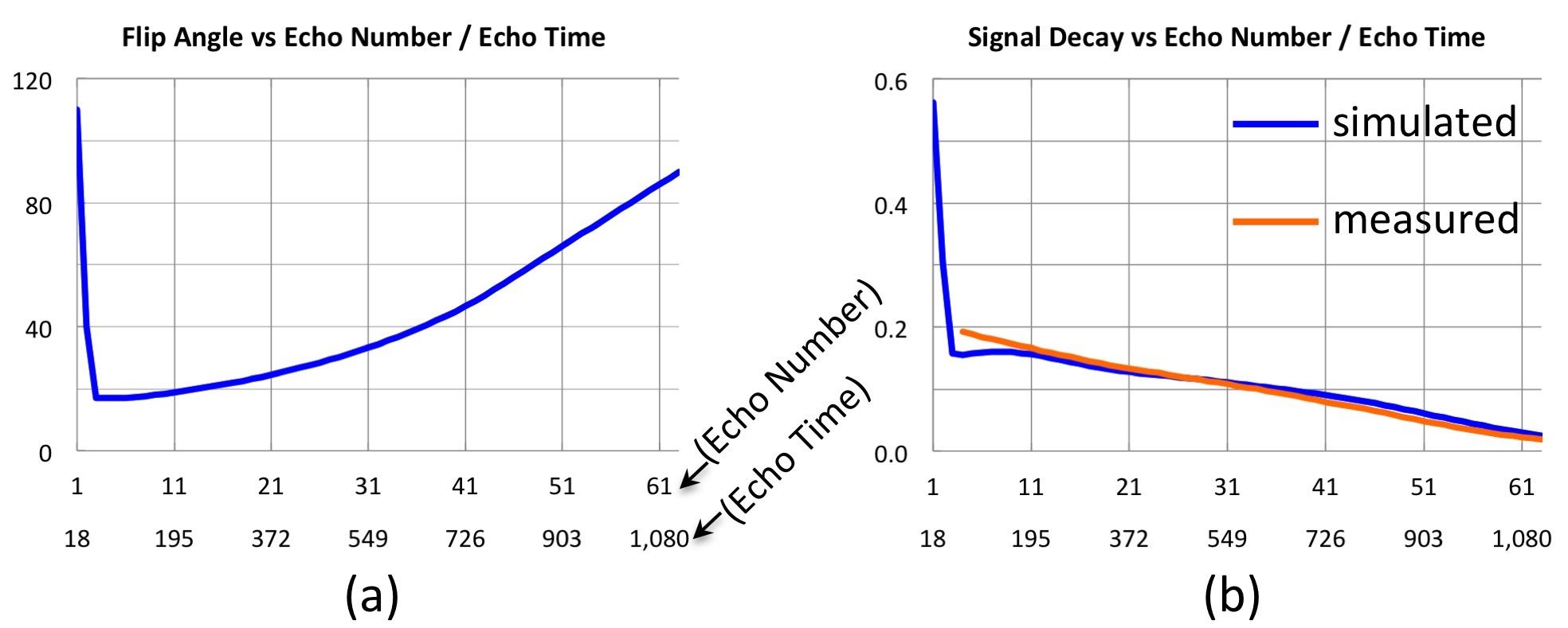
Flip Angle Schedule: With the conventional variable refocusing flip angle schedule, the first few (typically around 6) echoes are not stable and often discarded. Since short readout/echo space (ESP) is typically used with Cartesian1,2 or the spiral-out 3D TSE3 with variable refocusing flip angle, the degrading in scan efficiency is not significant. Nonetheless, long spiral readout is preferred for higher efficiency. This leads to long ESP, which implies the reduction in scan efficiency is no longer trivial. To mitigate this drawback, we adapt the variable flip angle scheme by using a very short initial ramp so that only the first 2 or 3 echoes are not stable and discarded, as shown in Fig. 2a. The simulated and measured signal evolution are shown in Fig. 2b.
Spiral data were acquired with FLAIR on a Philips 3T Ingenia scanner using the following parameters: FOV = 230x230x144 mm3, resolution = 1x1x3 mm3, TR = 4800 ms, TI = 1500ms, ADC = 14.4 ms, ESP = 17.7 ms, ETL = 60, equivalent TE = 149 ms. A stack-of-spirals k-space trajectory was used with the echo train distributed along the slice phase encoding direction. Reference Cartesian FLAIR (VISTA, vendor’s product version) was scanned with similar parameters except for FOV = 230x200x144 mm3, TI = 1650, ESP = 3.0 ms, ETL = 199, equivalent TE = 134 ms. Parallel imaging was not used for a fair comparison. The scan time was 5:12 and 7:26 for spiral and Cartesian scans, respectively. Spiral data were also acquired without concomitant phase compensation to demonstrate its necessity.
Results and Discussion
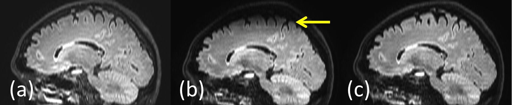
As shown in Fig 3, compared to the reference Cartesian image (3a), the loss of signal at off-center voxels is observed in the spiral image (yellow arrow in 3b, reformatted sagittal plane from axial data) collected without concomitant phase compensation. The signal loss is mostly eliminated (3c) by using the compensation technique, demonstrating its efficacy and necessity.
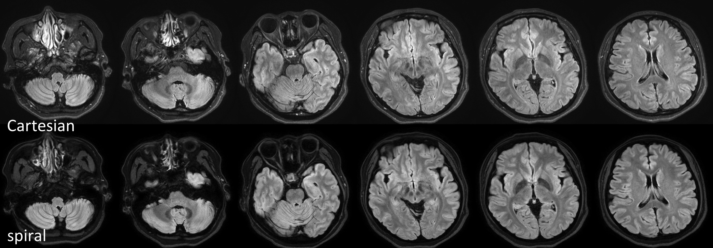
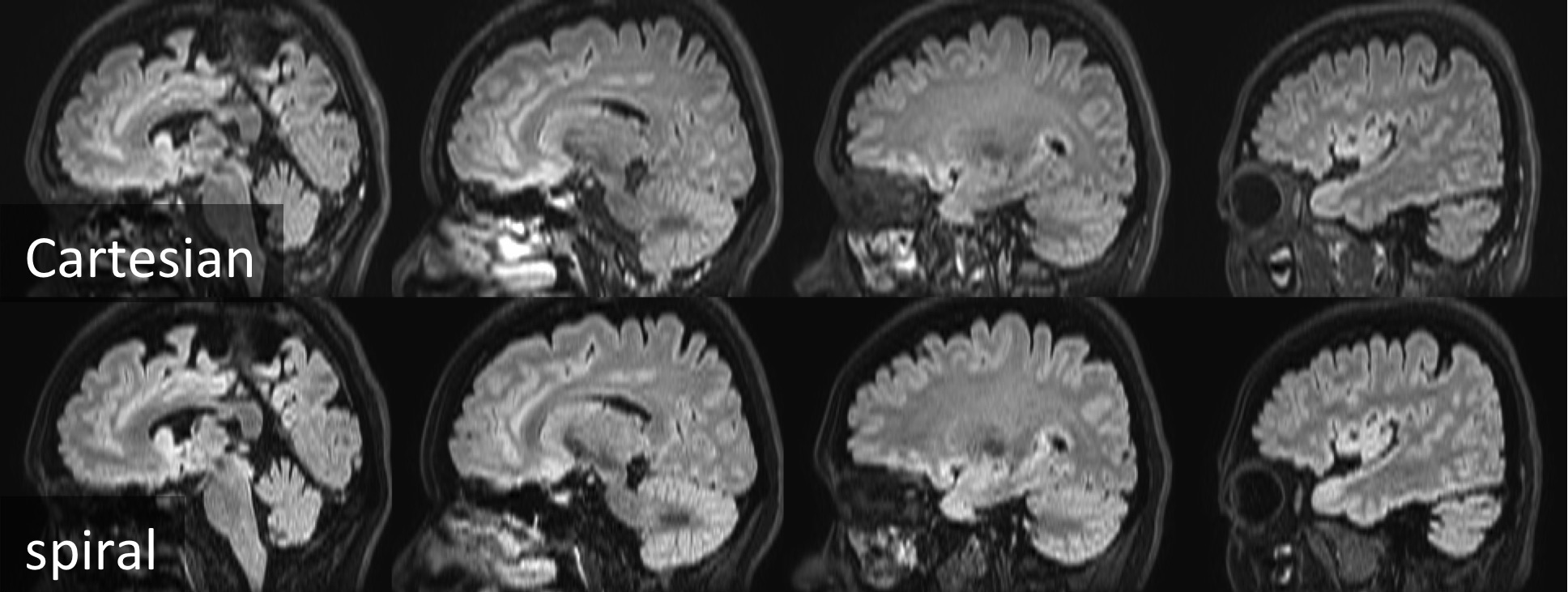
Figs. 4 and 5 compare the spiral data with the reference Cartesian data in the axial and reformatted sagittal planes, respectively. It is observed that the spiral images are comparable to the Cartesian references in terms of contrast, SNR, and sharpness. Note that the spiral acquisition is faster than the Cartesian scan. Scan time of spiral TSE can be further reduced by using parallel imaging, which is beyond the scope of this work.
Conclusion
The preliminary results demonstrate a promising 3D spiral-in/out TSE technique employing a long readout echo train and concomitant phase compensation.Acknowledgements
This work was funded by Philips Healthcare. The authors thank Dr. Gert van IJperen for helpful discussions.References
(1) Mugler JP. Optimized Three-Dimensional Fast-Spin-Echo MRI. J Magn Reson Imaging. 2014;39:745-767.
(2) Busse RF, Hariharan H, Vu A, et al. Fast Spin Echo Sequences With Very Long Echo Trains: Design of Variable Refocusing Flip Angle Schedules and Generation of Clinical T2 Contrast. Magn Reson Med. 2006;55:1030-1037.
(3) Fielden SW, Meyer CH, Mugler JP. Variable-Flip Angle 3D-Turbo Spin Echo Imaging Utilizing Spiral Acquisitions. Proceedings of ISMRM. 2011;19:2820.
(4) Li Z, Wang D, Robison RK, et al. Sliding-Slab Three-Dimensional TSE Imaging With a Spiral-In/Out Readout. Magn Reson Med. 2016;75:729-738.
(5) Hinks RS. Fast Spin Echo Prescan for MRI System. US5378985 (A), 1995.
(6) Zhou XJ, Du YP, Bernstein MA, et al. Concomitant Magnetic-Field-Induced Artifacts in Axial Echo Planar Imaging. Magn Reson Med. 1998;39:596-605.
(7) Zhou XJ, Tan SG, Bernstein MA. Artifacts Induced by Concomitant Magnetic Field in Fast Spin-Echo Imaging. Magn Reson Med. 1998;40:582-591.
Figures