3914
Characterization of a matrix gradient system using a magnetic field probe1Institute of Biomedical Engineering, National Taiwan University, Taipei, Taiwan, 2Medical Physics, Department of Radiology, University Medical Center Freiburg, Freiburg, Germany
Synopsis
Measuring GIRF using field probe and chirp gradient waveform is an efficient method to characterize the gradient behavior. We demonstrate that by measuring GIRF for each channel we are able to predict the response of simultaneously driven 12-channel gradient operation. Full characterization of the gradient system can be used to detect suboptimal matching of the amplifier and can be used to achieve desired performance also in such complex systems as matrix gradient coils.
Introduction
The concept of PatLoc (parallel imaging technique using localized gradients)1 stimulated the development of gradient coils with nonlinear spatial encoding magnetic fields (SEMs)2. Nonlinear SEMs have further catalyzed development of novel methods for dynamic shimming3, B1+ inhomogeneity mitigation4 and reduced field-of-view imaging5. Often, the efficacy of these methods critically depends on the accurate knowledge of the generated SEM fields. The recently developed matrix gradient system provides unprecedented flexibility in generating customized SEMs with 84 localized coil elements6. The initial experience with the coil has shown, that although only weak eddy currents could be observed, using multiple coil channels simultaneously presented a challenge. Therefore, a precise characterization based on the impulse response function (GIRF) for each gradient channel was deemed necessary. A magnetic field probe7 and chirp gradient waveform was used to estimate GIRF for 12 combined channels of the matrix gradient coil. We demonstrate that this method is able to predict the behavior of the coil when all channels are driven simultaneously.Methods
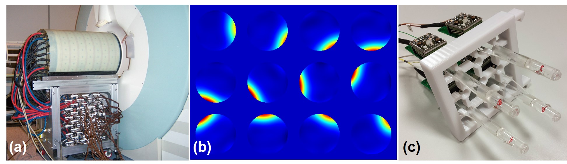
An actively-shielded matrix coil with 84 elements was constructed, assembled and cast in epoxy at our institution (Figure 1a). The complexity of the power and control electronics was reduced by assigning the 84 coil elements into 12 clusters, with 5 elements each, connected in series. The clusters were connected to 12 gradient power amplifiers (IECO, Helsinki, Finland). SEM maps for each group at the isocenter are shown in Figure 1b. Our home-made field probes are micro-coils with small NMR-active droplets (Figure 1c).To characterize the GIRF, we designed a 9-second chirp gradient waveform with a linear frequency sweep from 0Hz to 4000Hz and a current amplitude of 50A. This waveform was first divided into 90 segments with equal duration of 100ms and field probe signals were recorded while performing each segment of the gradient waveform. For the second part of the measurement, similar measurement with the residual 89 segments starting at 50 ms of the designed chirp waveform and ending at 8.95s was done. We eliminated the first 1 millisecond of the measured magnetic field evolution of each segment and then concatenated and averaged the remaining data to form the complete 9-second magnetic field evolution. The GIRF in the frequency domain was calculated as the ratio between the Fourier transform of estimated magnetic field by the Fourier transform of the designed chirp function. Thereafter GIRF of the simultaneously-driven channels was measured in two modes. Mode 1: all adjacent channels were driven using opposite currents such that the magnetic field at isocenter was minimized. Mode 2: all channels were driven using the same current polarity such that the magnetic field at isocenter was maximized.Results
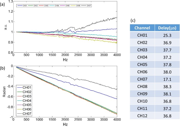
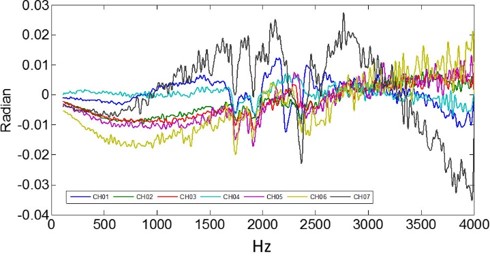
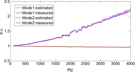
The magnitude and phase of the normalized GIRFs for 7 selected channels are shown in Figures 2a and 2b. The time delay (Figure 2c) of each channel can be estimated by the slope of the phase in Figure 2b. Channel 1 and 7 have a higher response at the higher frequencies and those channels also show a substantially shorter delay. Figure 3 shows the residual phase of GIRF after subtracting the linear trend. Each channel showed distinct behavior but they all have the same dip near 1750 and 1900 Hz, probably associated with mechanical resonances. Figure 4 shows the measured magnitude GIRF of mode 1 and 2 along with the estimated GIRF. The estimation based on the individual channels is able to pick up characteristic features of the two modes, although the RMS error for mode 1 is somewhat larger (1.6% vs. 0.3%). The distinctly different time delay of channel 1 and 7 (Figure 2b) explain the increased gradient response at high frequencies of mode 1, because the magnetic field is canceled as expected at low frequencies but not at high frequencies.Discussion
We measured GIRF for each gradient channel and show that the individually measured GIRF can be used to predict the gradient response when the 12 gradient channels are driven simultaneously. Despite of the fact that the present setup has two anomalous channels, showing very different GIRFs, two different combined drive modes can be simulated with high accuracy. In this study, we only showed the GIRF using one field probe to characterize temporal gradient behavior. Due to eddy currents and gradient channel coupling, measuring GIRFs using multiple probes with suitable modeling of spatial responses can further enhance the prediction of the spatio-temporal responses8. However, the modeling of spatial responses for our system is complicated; therefore, a substantially higher number of field probes may be required for a valid estimation.Acknowledgements
No acknowledgement found.References
1. Hennig, J., et al., Parallel imaging in non-bijective, curvilinear magnetic field gradients: a concept study. Magnetic Resonance Materials in Physics, Biology and Medicine, 2008. 21(1-2): p. 5-14.
2. Welz, A., et al., Development and characterization of an unshielded PatLoc gradient coil for human head imaging. Concepts in Magnetic Resonance Part B: Magnetic Resonance Engineering, 2013. 43(4): p. 111-125.
3. Juchem, C., et al., Multi-slice MRI with the dynamic multi-coil technique. NMR in Biomedicine, 2015. 28(11): p. 1526-1534.
4. Hsu, Y.C., et al., Mitigate B1+ inhomogeneity using spatially selective radiofrequency excitation with generalized spatial encoding magnetic fields. Magnetic resonance in medicine, 2014. 71(4): p. 1458-1469.
5. Witschey, W.R., et al., Localization by nonlinear phase preparation and k-space trajectory design. Magnetic resonance in medicine, 2012. 67(6): p. 1620-1632.
6. Jia, F., et al., Performance evaluation of matrix gradient coils. Magnetic Resonance Materials in Physics, Biology and Medicine, 2016. 29(1): p. 59-73.
7. Barmet, C., et al., A transmit/receive system for magnetic field monitoring of in vivo MRI. Magnetic resonance in medicine, 2009. 62(1): p. 269-276.
8. Vannesjo, S.J., et al., Gradient system characterization by impulse response measurements with a dynamic field camera. Magnetic resonance in medicine, 2013. 69(2): p. 583-593.
Figures