3910
Spatiotemporal Magnetic Field Monitoring with Hall Effect Sensors1National Magnetic Resonance Research Center (UMRAM), Bilkent University, Ankara, Turkey, 2Electrical and Electronics Engineering, Bilkent University, Ankara, Turkey
Synopsis
Hall effect sensors can be used to monitor the spatiotemporal field dynamics. However, measurement of the z component of the magnetic field (Bz) requires very large dynamic range for the Hall effect sensors due to superposition of encoding fields with main magnetic field (B0). Instead, we propose to measure the transverse components of the magnetic field in several spatial positions to reconstruct spatiotemporal dependency of Bz and we have demonstrated reconstruction of the first order spherical harmonic field distributions.
Purpose and Introduction
Due to hardware imperfections and physical limitations, magnetic fields during an imaging sequence is never exactly same as it is expected by a pulse programmer. NMR probes have already been used to monitor both spatial and temporal dependency of the magnetic fields which leads to estimation of the correct k-space trajectory to be used in the image reconstruction1. Later dynamic field camera has been developed to measure field dynamics up to third order spherical harmonics including 16 NMR probes2. Although, NMR is a very suitable way of field monitoring, requirement of spectrometer for the NMR probes, transmit and low noise RX chain for all probes as well as demanding constructing process of the NMR probes3 might lead to a significant cost increase.
As an alternative, we propose to use Hall effect sensors to monitor the spatiotemporal field dynamics. However, measurement of the z component of the magnetic field (Bz) requires very large dynamic range for the Hall effect sensors due to superposition of encoding fields with main magnetic field ($$$B_0$$$). Instead, we propose to measure the transverse components of the magnetic field in several spatial positions to reconstruct spatiotemporal dependency of $$$B_z$$$.
Methods
Hall effects sensors consist of a current carrying Hall element which is perpendicular to measured magnetic field. Hall effect sensors might be used to measure directly Bz inside the MRI scanner; however, field deviations on the order of ppms of the B0 can be effective in the images and should be monitored. Such a dynamic range is not practical and will result in either very low sensitivity or saturation of the sensor. Ideally, when Hall elements are aligned to measure concomitant fields, there will be no interference with the main magnetic fields which will not cause saturation and high sensitivity can be maintained. Additionally, if the direction of the current is aligned with the z-direction inside the MR scanner, Maxwell equation can be written in the form which directly leads to Equation 1.
$$\nabla \times B = \hat{a} _{x} (\frac{\partial B_{z}}{\partial y}-\frac{\partial B_{y}}{\partial z})+\hat{a} _{y} (\frac{\partial B_{z}}{\partial x}-\frac{\partial B_{x}}{\partial z})+\hat{a} _{z} (\frac{\partial B_{y}}{\partial x}-\frac{\partial B_{x}}{\partial y}) = \hat{a} _{z} \mu_{0}J\quad(1)$$
$$\frac{\partial B_{z}}{\partial y}=\frac{\partial B_{y}}{\partial z}\quad \quad \frac{\partial B_{z}}{\partial x}=\frac{\partial B_{x}}{\partial z}$$
$$\nabla \cdot B = \frac{\partial B_{x}}{\partial x}+\frac{\partial B_{y}}{\partial y}+\frac{\partial B_{z}}{\partial z} =0 \quad(2)$$
$$\frac{\partial B_{z}}{\partial z} = -(\frac{\partial B_{x}}{\partial x}+\frac{\partial B_{y}}{\partial y})$$
Furthermore, last partial derivative of the Bz can be determined from the zero divergence condition as in Equation 2. Therefore, knowledge of transverse fields are adequate to determine the all partial derivatives of the Bz, in other words $$$\nabla$$$ Bz. However, spatial DC component cannot be determined with this formulation. Since spatially constant term is not used to calculate Bz, field measurement at three point is adequate to measure first order spherical harmonics of Bx and By. Afterwards, by using Equation 1 and 2, Bz can be calculated up to same order spherical harmonics with Bx and By.
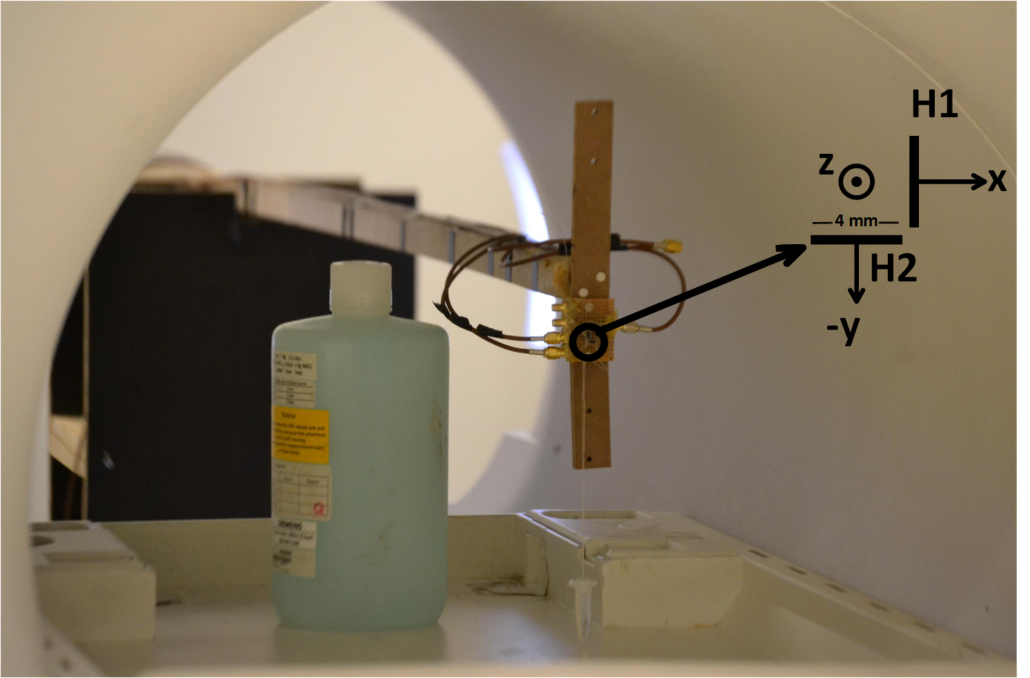
Two commercially available Hall effect sensors (DRV5053, Texas Instruments) with 20kHz bandwidth and 23mV/mT sensitivity are used to measure magnetic field in x and y directions as in Fig.1 and data is digitized with the ADC of an oscilloscope (Ds07104B, Agilent Technologies). Experiments are performed with a 3T MRI Scanner (Tim Trio, Siemens). In order to demonstrate the proof of concept, sensors are placed at 3 different positions in 3 different scans due to insufficient number of sensors. At each scan, y-gradient is applied with strength of 20mT/m, rise and fall times of 2ms and flat top duration of 10ms.
Results
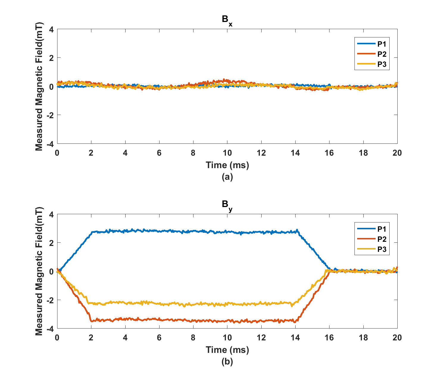
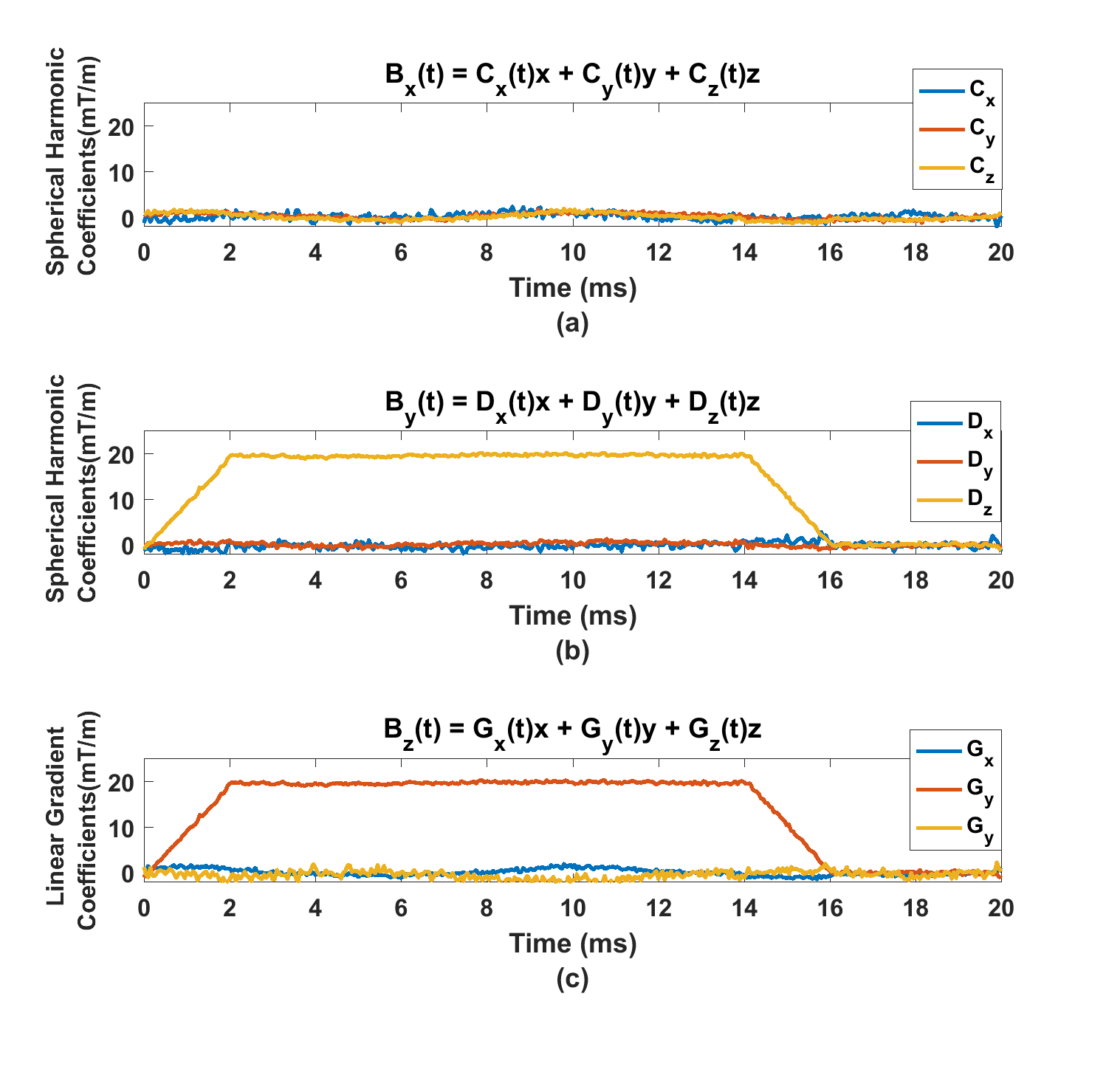
Magnetic field in x and y directions are measured in 3 different spatial locations as in Fig. 2. By using the magnetic field levels at each time and inverse of the probing matrix1, spatiotemporal dependency of Bx and By are constructed up to first order spherical harmonics as in Fig.3a and Fig.3b. After Bx and By are determined, Bz is determined using the Equation 1 and 2 and it is shown in Fig.3c. In Fig.3c, it is shown that Gy gradient is detected as applied in the sequence which shows the feasibility of the proposed method.Discussion
Proposed technique cannot measure the spatial DC component. Only one channel NMR probe can be used as a reference point to estimate the DC component. Our method requires double number of sensors compared to NMR probes because field is measured in two directions which leads to an advantage of measuring concomitant field directly without any processing.Conclusion
Spatiotemporal magnetic field monitoring inside a MRI scanner with Hall effect sensors is possible.Acknowledgements
No acknowledgement found.References
1. Barmet C, De Zanche N, Pruessmann KP. Spatiotemporal magneticfield monitoring for MR. Magn Reson Med 2008;60:187–197.
2. Dietrich BE, Brunner DO, Wilm BJ, Barmet C, Gross S, Kasper L, Haeberlin M, Schmid T, Vannesjo SJ, Pruessmann KP. A field camera for MR sequence monitoring and system analysis. Magn Reson Med 2015. doi: 10.1002/mrm.25770.
3. De Zanche N, Barmet C, Nordmeyer-Massner J, Pruessmann KP. NMR probes for measuring magnetic fields and field dynamics in MR systems. Magn Reson Med 2008;28:1654–1664.
Figures