3909
Implementation of a Gradient Pre-emphasis Based on the Gradient Impulse Response Function1Department of Diagnostic and Interventional Radiology, University of Würzburg, Würzburg, Germany, 2X-Ray & Molecular Imaging Lab, Technical University Amberg-Weiden, Weiden, Germany, 3Siemens, Erlangen, Germany
Synopsis
The gradient impulse response function (GIRF) completely characterizes the gradient system as a linear and time-invariant (LTI) system, and has recently been used to correct for distorted k-space trajectories in image reconstruction. We now report on the implementation of a GIRF-based pre-emphasis, which is resulting in gradient waveforms already matching the desired k-space trajectory and rendering post-corrections obsolete. The method was successfully tested in a sequence with modulated phase-encoding gradients, as for example used in Wave-CAIPI.
Purpose
K-space trajectories are frequently impaired by eddy currents, readout timing and amplifier errors and other system imperfections. The gradient impulse response function (GIRF) has been used to describe the distorted k-space trajectory for image reconstruction [1]. Purpose of this work was to use the GIRF to determine the pre-emphasis for an undistorted gradient output and intended k-space trajectory. As an example, a sequence with phase-encoding gradient modulation as it is used for Wave-CAIPI [2] was corrected.
Methods
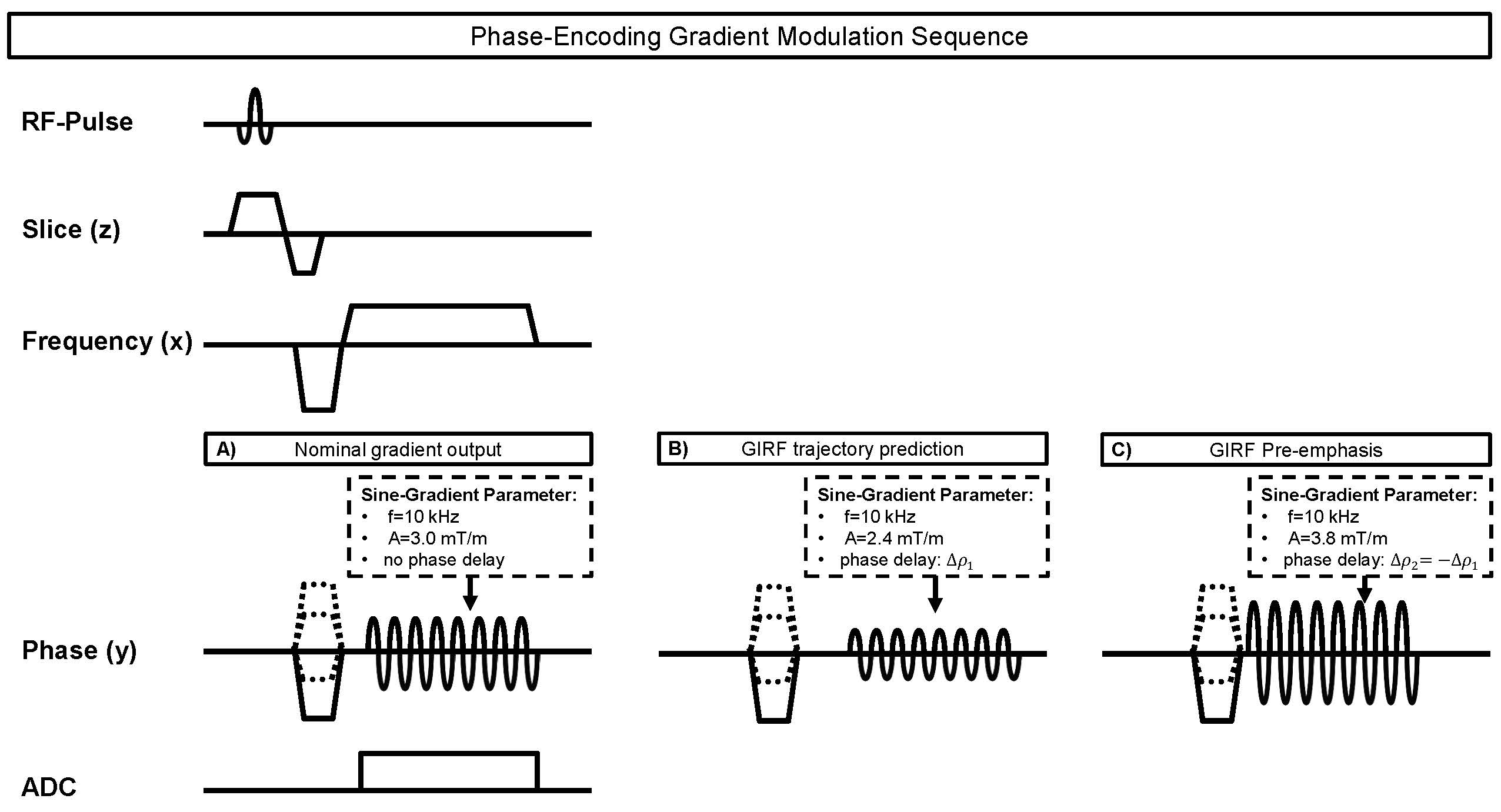
The gradient echo sequence with phase-encoding gradient modulation (Fig. 1) [3] was implemented on a 3T MR system (MAGNETOM Prisma, Siemens Healthcare, Erlangen, Germany) and subsequently applied on a structural phantom and on in-vivo head measurements. Compared to a standard gradient echo sequence, the used prototype sequence plays out an additional oscillating harmonic gradient waveform in phase-encoding direction during data acquisition. The frequency of the sine-wave was set to 10 kHz, and the intended maximum gradient amplitude (nominal amplitude) was 3.0 mT/m. Other sequence parameters were: TR = 5.4 ms (TR = 20.0 ms for the in-vivo measurements), TE = 2.6 ms, read-out bandwidth = 930 Hz/pixel. A separate GIRF of the MR system for each spatial dimension was determined using triangular input gradients [4, 5]. 12 different input gradients (duration 100 – 320 µs, slew rate = 180 T/m/s) were played out, and the system’s response was measured in two parallel slices of a spherical phantom. The output gradient was then calculated using the difference in phase evolution between both slices. The relevant measurement parameters were set to: TR = 8.0 s, slice thickness = 3 mm, slice gap = 33 mm, flip-angle = 90°, read-out bandwidth = 100 Hz/pixel, 60 averages. For the test sequence with phase-encoding gradient modulation, acquisitions were first performed using the intended gradient waveform (i.e. the nominal gradient output, Fig. 1A). Images of the structural phantom and the in-vivo measurements were then reconstructed using convolution gridding [6] and the trajectory derived from 1A. Subsequently, the GIRF was used to correct the gradient waveform played out in 1A in post-processing (i.e. the GIRF trajectory prediction as proposed in [5], Fig. 1B), and images were reconstructed using the updated k-space trajectory. Finally, corresponding acquisitions were performed using gradient waveforms additionally corrected by a GIRF-based pre-emphasis (Fig. 1C), and images were reconstruction using the trajectory derived from the nominal waveform in 1A.Results
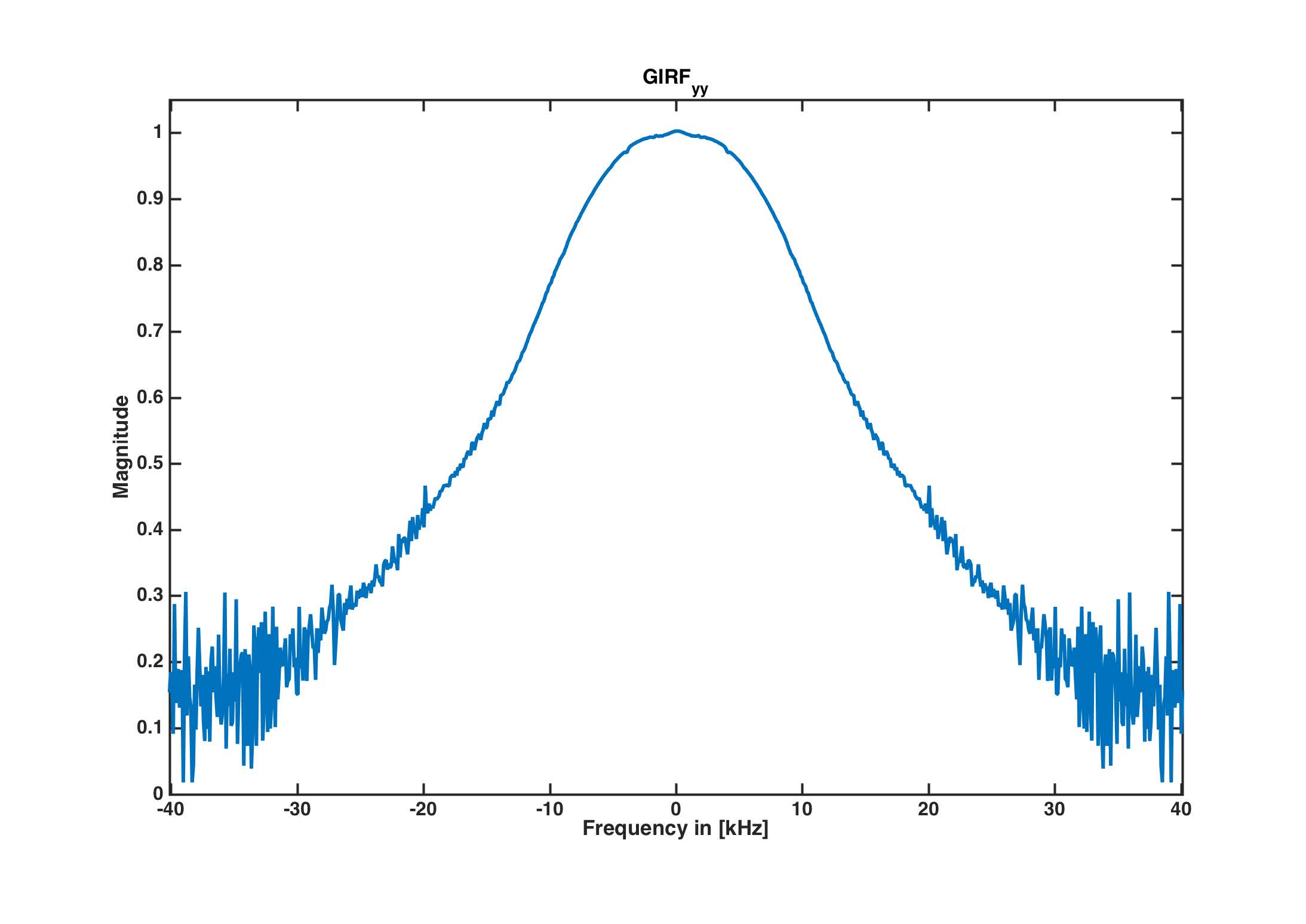
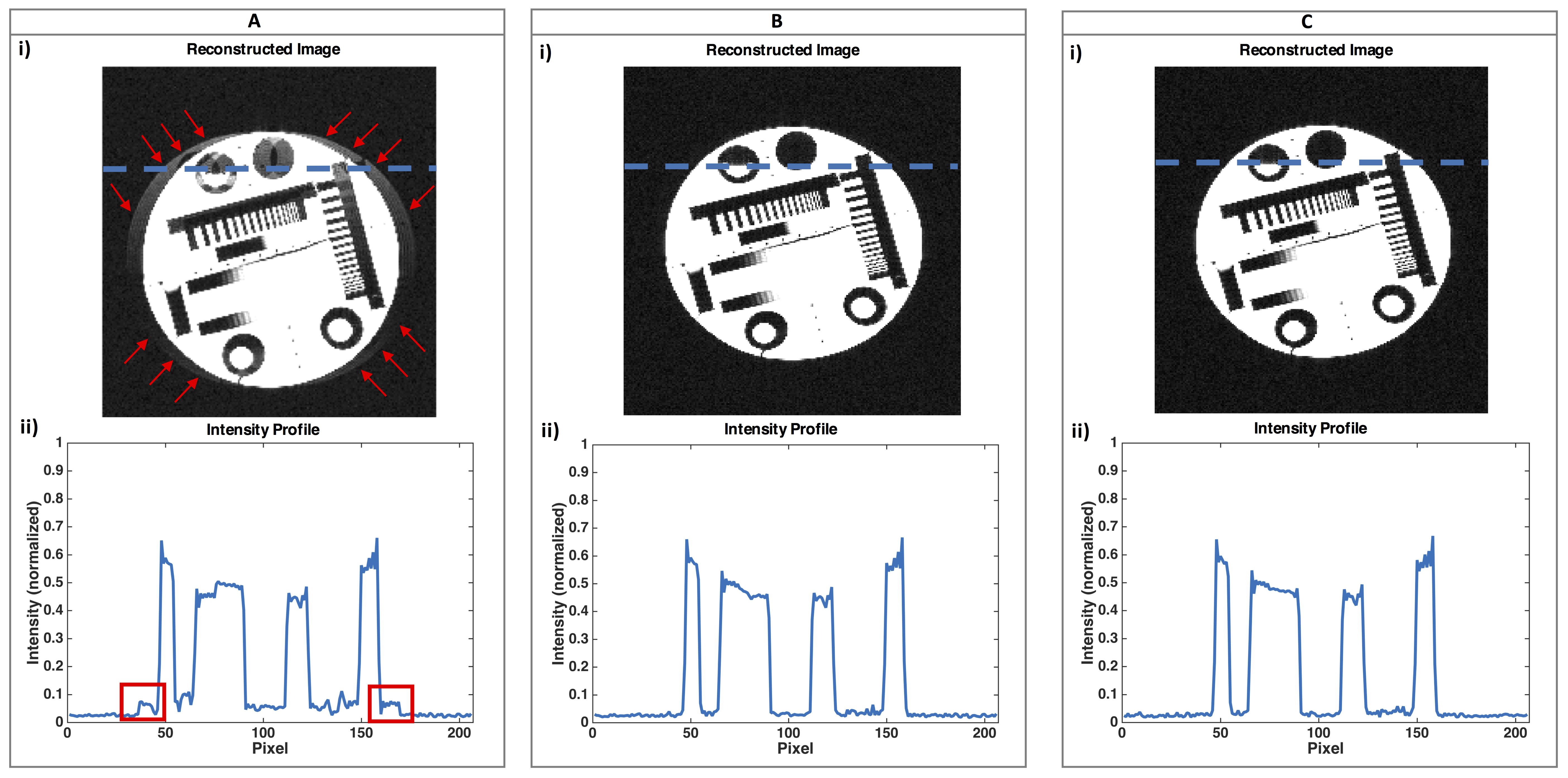
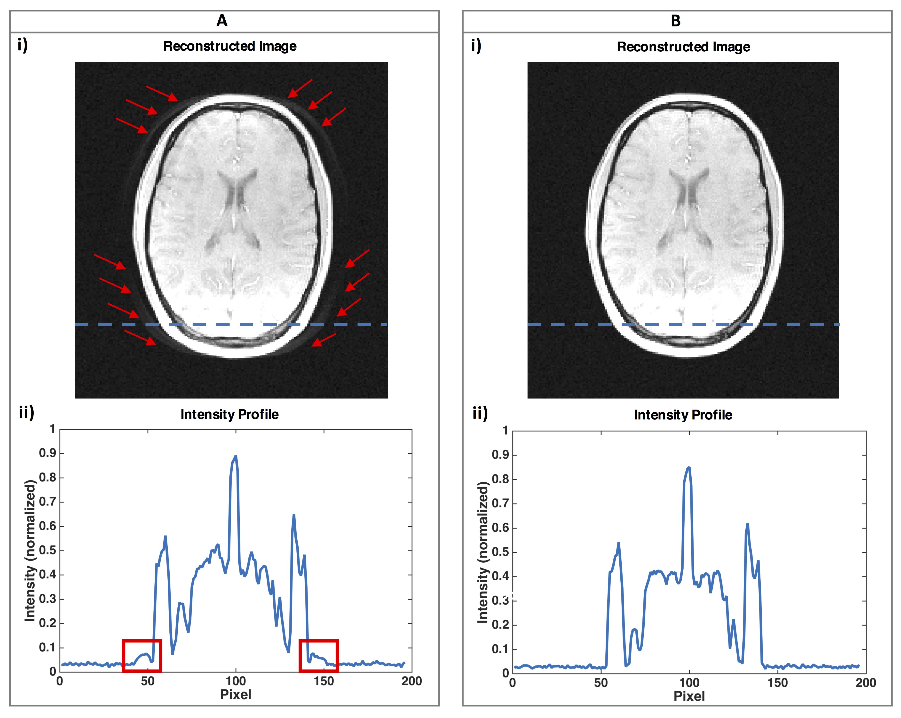
The magnitude of the relevant GIRFyy is shown in Fig. 2. At a frequency of 10 kHz, the GIRFyy amplitude dropped to 79 % with a phase of 0.04 rad. This means that the amplitude of the actually played out oscillating gradient drops to 0.79 · 3.0 mT/m = 2.4 mT/m (GIRF trajectory prediction, Fig. 1B). To reach an actually played out oscillating gradient with maximum amplitude of 3.0 mT, it was necessary to apply a GIRF-based pre-emphasis on the input waveform leading to a maximum amplitude of 3.0/0.79 mT/m = 3.8 mT/m (Fig. 1C). Figure 3 shows the reconstructed phantom images (i), together with the intensity profile in frequency-encoding direction at the position of the dashed line (ii). Ghosting-artifacts are present if no correction is applied (Fig. 3A, i, ii). When considering the reduced frequency transmission rate and delay of the gradient system within a GIRF-predicted correction of the trajectories in post-processing, the image artifacts are suppressed (Fig. 3B, i, ii). The image acquired using the GIRF-based pre-emphasis can be reconstructed free from artifacts using the initially intended trajectory (Fig. 3C, i, ii). The in-vivo head acquisitions are showing equivalent results: ghosting-artifacts, which are present in the image without any correction (Fig. 4A) can be removed by applying a gradient waveform corrected by a GIRF-pre-emphasis (Fig. 4B).Discussion & Conclusion
Due to the sinusoidal gradient, consisting of only one frequency component, the sequence with phase-encoding gradient modulation is a straightforward example for a GIRF-based pre-emphasis implementation. While this type of sequence has gained a lot of interest recently [2, 7, 8], its application is still rather uncommon. However, applying a pre-emphasis based on the GIRF information can in principle be applied to any arbitrary sequence type. In summary, our results prove that the gradient impulse response function information can serve for a novel pre-emphasis.Acknowledgements
No acknowledgement found.References
[1] Vannesjo S.J. et. al. Image Reconstruction Using a Gradient Impulse Response Model for Trajectory Prediction. MRM. 2016;76:45-58.
[2] Bilgic B. et. al. Wave CAIPI for Highly Accelerated 3D Imaging. MRM. 2015;73:2152-2162.
[3] Hinks R.S., Xiang Q-S., Henkelman R.M. Ghost Phase Cancellation with Phase-encoding Gradient Modulation. MRM. 1993;3:777-785.
[4] Liu H., Matson G.B. Accurate Measurement of Magnetic Resonance Imaging Gradient Characteristics. Materials (Basel). 2014;7:1–15.
[5] Campbell-Washburn AE. et. al. Real-time distortion correction of spiral and echo planar images using the gradient system impulse response function. MRM. 2016;75:2278-2285.
[6] Fessler J.A., Sutton B.P. Nonuniform fast Fourier transforms using min-max interpolation. IEEE Transactions on Signal Processing. 2003;51:560-572.
[7] Cauley S.F. Autocalibrated wave-CAIPI reconstruction; Joint optimization of k-space trajectory and parallel imaging reconstruction. MRM. 2016. [Epub ahead of print, doi: 10.1002/mrm.26499].
[8] Liebig P., Heidemann R.M., Porter D.A. Echo-planar imaging on a true zig-zag trajectory. ESMRMB Congress 2015. S.100.
Figures