3854
Improved Simultaneous Multislice Pulse Design Directly Constraining Peak RF Amplitude1Biomedical Engineering, University of Michigan, Ann Arbor, MI, United States, 2BIomedical Engineering, University of Michigan, Ann Arbor, MI, United States, 3Electrical Engineering and Computer Science, University of Michigan, Ann Arbor, MI, United States
Synopsis
In this abstract, we propose the design of SMS RF pulses using a new method based on the small-tip angle approximation that directly constrains peak amplitude using a least-square optimization. We compare our proposed method to the equivalent phase-modulated Shinnar-Le Roux (SLR) SMS pulse with optimized phase scheduling for minimal RF power. Our proposed method provides lower simulation error than SLR-based designs at equivalent pulse lengths and same error for shorter pulse lengths that are unrealizable (in the peak amplitude sense) with the SLR-based approach. In experiment we show sharp excitation slice profiles for our SMS designs.
Purpose
Simultaneous multislice (SMS) excitation for MRI is an effective means of accelerating imaging. Even still, SMS RF pulses have flip angle and multiband (MB) factor limitations that are usually dictated by either the RF pulse peak amplitude limit or power deposition, which both roughly scale linearly with the number of slices1. In SMS applications using longer imaging TR’s such as fMRI, the main RF limit is peak amplitude, rather than SAR, particularly at higher MB factors. In this abstract, we propose a new SMS RF pulse design method that uses the small-tip angle (STA) approximation2 and directly constrains peak amplitude using a least-squares optimization. Existing methods only indirectly reduce peak RF amplitude through Tikhonov regularization parameter tuning3, exhaustive search techniques4, and optimized phase scheduling based on MB factor1. Our method adapts to RF design parameters such as flip angle (up to 90°) and multiband factor while guaranteeing to meet specified hardware constraints.Methods
We design an SMS RF pulse by solving the following constrained optimization problem:
$$\hat{\bf{b}}=\mathrm{argmin}(\bf{b})\; \vert\vert \bf{Ab}-\bf{d} \vert \vert_{\bf{W}}^{2}\; \mathrm{s.t.}\;\vert\vert\bf{b}\vert\vert_{\infty}\leq\mathrm{b_{max}}$$
where b is the RF pulse, A is the small-tip angle system matrix with slice selective k-space trajectory, d is our target multiband pattern, and bmax is the peak RF amplitude limit, 0.2G. Our target pattern d contains 3mm slices spaced every 15mm and each slice is phase-modulated according to Wong 20121. We solve this optimization problem quickly (1-2sec) using FISTA5.
We compare our SMS pulse design method with SMS pulses created by phase-modulating and summing slice-selective pulses created with the Shinnar-LeRoux (SLR) algorithm6. The SLR-based SMS pulses were also modulated to minimize peak power1. For a given number of slices, we found the shortest pulse length for which the SLR-based pulse still meets the RF amplitude limit. We then designed an SMS RF pulse using our proposed constrained method for that same pulse length. Finally, we designed a constrained RF pulse for a shorter pulse length that had the same total simulated magnitude normalized root sum-of-squares error (NRSSE) as the longer SLR-based pulse. All pulses had a time-bandwidth product of 4.
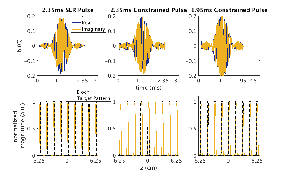
We show results here for 9-MB factor SMS pulse design with pulse lengths of 1.95ms and 2.35ms for the constrained RF designs and 2.35ms for the SLR-based design. All pulses were evaluated via simulation using the small-tip angle approximation (mxy≈Ab) and Bloch simulation. These pulses were then used in a 2D GRE acquisition (α/TE/TR=55°/4.8ms/300ms) to scan a gel ball phantom on our 3T GE MRI scanner.
Results
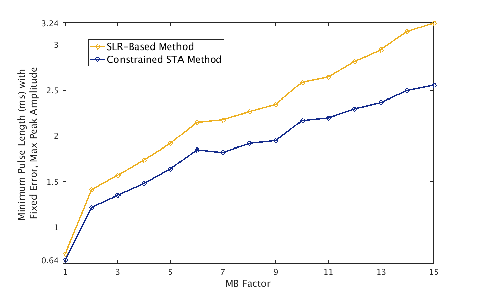
Figure 1 plots the minimum pulse length possible for a fixed peak amplitude and total magnitude NRSSE as a function of MB factor. This plot compares this relationship for both SLR-based designs and the proposed constrained method.
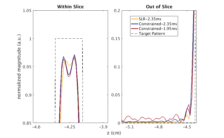
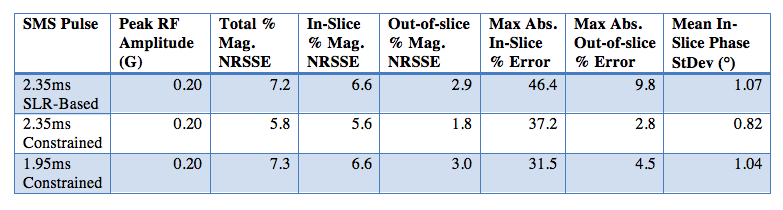
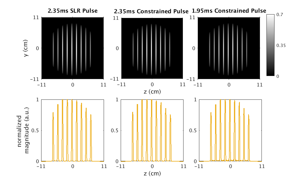
Figure 2 shows the SMS pulse RF waveforms and simulated magnetization magnitude for a 9-MB pulse comparing the SLR-based and proposed constrained STA design methods. Figure 3 shows magnified views of these simulated magnetization magnitudes at the top of the slice and directly outside the slice profile. Table 1 reports the obtained peak RF amplitude in Gauss, mean standard deviation of phase within slice, the percent magnitude NRSSE values for total magnetization as well as in-slice and out-of-slice design regions, and maximum percent absolute error both in-slice and out-of-slice. Finally, Figure 5 shows the 2D experimental slice images from the SMS pulse designs as well their 1D slice profile.
Discussion
By designing SMS pulses with a constrained STA method, we are able to design pulses that directly meet RF peak amplitude limits. Figure 1 shows that for the same NRSSE and peak amplitude, our method will produce shorter pulse lengths than an SLR-based design. In the specific case of 9-MB pulses, for the same length pulse, our proposed method achieves lower magnitude NRSSE and for an equivalent total magnitude NRSSE the pulse is 17% shorter (Table 1). In experimental results, we observe sharp slice profiles for all design approaches. This establishes the design advantage and experimental feasibility of our proposed method.Conclusion
We compare our proposed method to the equivalent phase-modulated SLR SMS pulse with optimized phase scheduling for minimal RF peak power. Our proposed method provides lower simulation magnitude NRSSE than SLR-based designs at equivalent pulse lengths and same NRSSE for shorter pulse lengths that are unrealizable (in the peak amplitude sense) with the SLR-based approach. We also show the sharp, experimental slice profiles of our SMS pulse designs. In the future we will incorporate these designs into a fMRI protocol for high MB-factors and adapt our constrained method for large-tip angle design.Acknowledgements
We would like to acknowledge Research Scientist Jon-Fredrik Nielsen for his help with experiments and thoughtful discussions.
References
1. Wong E. Optimized phase schedules for minimizing peak RF power in simultaneous multi-slice excitation pulses. Proc. Intl. Soc. Mag. Reson. Med. 2012; 20.
2. Pauly J, Nishimura D, and MacoVski A. A k-space analysis of small-tip-angle excitation. J. Mag. Reson. 1989; 81:43-56.
3. Aigner CS, Clason C, Rund A, Stollberger R. Efficient high-resolution RF pulse design applied to simultaneous multi-slice excitation. J. Mag. Reson. 2016; 263:33-44.
4. Sharma A, Lustig M, Grissom WA. Root-flipped multiband refocusing pulses. Mag. Reson. Med. 2016; 75(1):227-37.
5. Beck A, Teboulle, M. A Fast iterative shrinkage-thresholding algorithm for linear inverse problems. SIAM J. Imaging Sci. 2009; 2(1):183-202.
6. Pauly J, Le Roux P, Nishimura D, Macovski A. Parameter relations for the Shinnar-Le Roux selective excitation pulse design algorithm. IEEE Trans. Med. Imaging. 1991; 10(1):53-65.
Figures