3723
A time domain signal equation for multi-echo spin-echo sequences with arbitrary exciation and refocusing angle and phase1Institute of Medical Engineering, Graz University of Technology, Graz, Austria
Synopsis
T2 quantification with multi-echo spin-echo sequences is often hampered by flip angle inhomogeneities and non-rectangular slice profiles. Here, we present a novel time domain signal equation for multi-echo spin-echo sequences with arbitrary excitation and refocusing flip angles and phases. To evaluate the equation simulations and phantom measurements were compared. Excellent agreement was found for the simulated and measured evolution of the transverse magnetization across the slice profile in a CP and a CPMG sequence. T2 mapping using the proposed signal equation and the incorporation of scanner specific RF pulse shapes will greatly improve T2 quantification accuracy.
Introduction
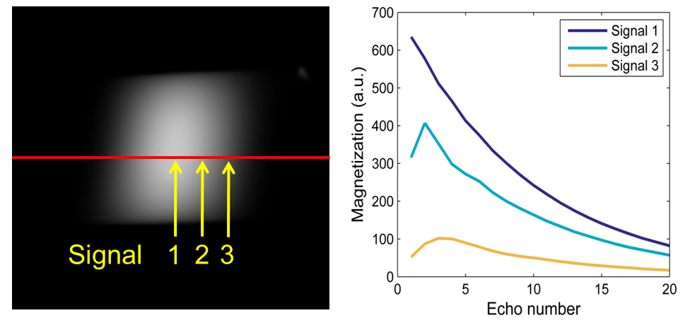
In quantitative MRI multi-echo spin-echo (MESE) sequences are frequently used for T2 mapping. However, the accuracy of the estimated T2 values is compromised by the inhomogeneity of the B1 field and non-rectangular slice profiles which lead to stimulated echoes that alter the expected mono-exponential signal decay (see Fig. 1). The CPMG phase relationship can compensate for errors if the flip angle deviations are small which is generally not the case for slice selective sequences. There exist various elaborate models that account for these deficiencies, such as simulations by the Bloch equations [1], the Extended Phase Graph algorithm (EPG) [2], or the so called Generating functions (GF) algorithm [3]. All approaches have their benefits and limitations, such as the iterative nature for the Bloch equations or EPG, or the need of a discrete Fourier transform (DFT) for the GF which can lead to truncation/leakage artifacts in the computed signal (especially for long T2). In this work we present a novel signal equation in the time domain, accounting for B1 and slice profile errors, as well as arbitrary phase relationships between excitation and refocusing pulses, yielding the accurate signal evolution for sequences that are not purely CPMG or CP, but a mixture of both.Theory and methods
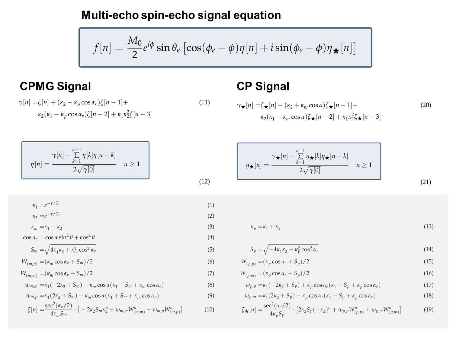
The derivation of the presented time domain formula is based on the GF formula, which is a closed form solution to the signal evolution in the so called z-domain (computed using the z-transform). The GF formula can be computed by solving a recurrence relation for the magnetization vector relating the (n+1)th echo to the nth echo [4]. One can evaluate this equation for a number of equidistant points around the unit circle (z=exp(ψk)) and subsequently apply the DFT to compute the echo amplitudes.
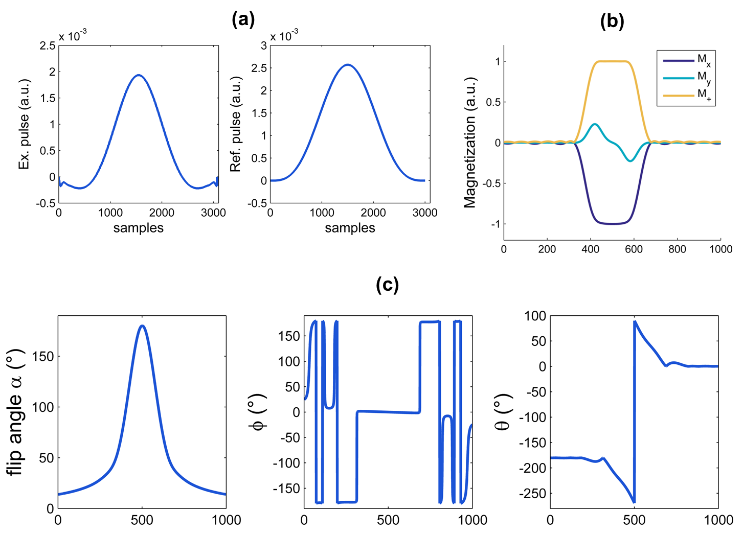
One can also try to analytically transform this equation back to the time domain (inverse z-transform) to obtain a closed form solution. However, the complicated form of the GF does not permit a direct inversion. Nevertheless, using the the convolultion property of the z-transform (x[n]*x[n] ↔X(z)2) one can obtain a time domain formula γ[n]=η[n]*η[n], whereas deconvolution of the signal η[n] with itself has to be carried out. The detailed equations and parameters and final result for the MESE signal f[n] are given in Fig. 2. The presented formula accounts for an arbitrary excitation profile and phase (Fig. 3 (b)) as well as arbitrary refocusing pulse angles and rotation axes (Fig. 3 (c)). Using the forward SLR algorithm one can compute all essential parameters included in the model such that the signal evolution of a whole slice profile can be simulated. In this work we compared simulations of the slice profile evolution with measured data for a CPMG (excitation about the x-axis, refocusing about y-axis) and a CP sequence (both excitation and refocusing about the y-axis). Data of a Gadolinium doped water phantom (T2=111 ms, T1=140 ms) were acquired on a 3T scanner (Skyra, Siemens) using a MESE sequence (echo spacing τ=12 ms, TR = 1000 ms, nominal excitation flip angle 90° and refocusing flip angle 180°) with the read out gradients in slice-direction to obtain the slice profile.
Results
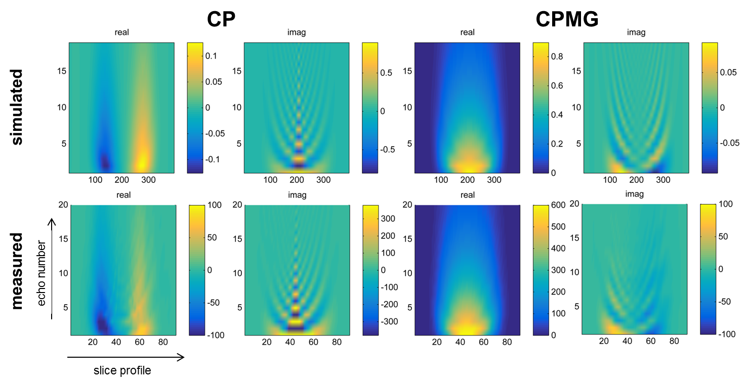
Fig. 4 shows a comparison of measured and simulated slice profile evolutions for a CPMG (phase angle between refocusing and excitation pulse is 90°) and a CP sequence (phase angle 0°). For a CPMG sequence the real part of the signal exhibits a rather smooth decay curve, whereas the imaginary part that originates in the Mx component of the excitation slice profile oscillates between positive and negative values. The same is true for the CP sequence. In general, the CPMG sequence yields higher signal amplitudes owing to the 90° phase relation that compensates for small flip angle deviations. In contrast, in CP type sequences these errors accumulate.Discussion
In this work we presented a complete signal equation for MESE sequences accounting for all excitation and refocusing pulse parameters (as well as M0, T1 and T2). The comparison of measurements and simulations show excellent agreement. Implementation of the formula is straightforward (evaluation of 6 exponential functions, adding together time shifted versions thereof, and deconvolving the signal) and lacks the deficiencies of the original GF approach (no DFT needed). We believe that this method is a breakthrough for T2 fitting with slice selective echo trains. By incorporating scanner specific RF pulse shapes T2 accuracy and comparability of T2 values between studies, scanners and sites is greatly improved.Acknowledgements
BioTechMed Graz, Graz, Austria
supported by the Austrian Science Fund (FWF) under grant SFB F3209-18
References
[1] N Ben-Eliezer et al., Rapid and accurate T2 mapping from multi–spin-echo data using Bloch-simulation-based reconstruction. Magn Reson Med 73(2):809-817, 2015.
[2] M Lebel et al., Transverse relaxometry with stimulated echo compensation. Magn Reson Med 64(4):1005-1014, 2010.
[3] A Petrovic et al., Closed-form solution for T2 mapping with nonideal refocusing of slice selective CPMG sequences. Magn Reson Med 73(2):919-827, 2015.
[4] N Lukzen et al., The generating functions formalism for the analysis of spin response to the periodic trains of RF pulses. Echo sequences with arbitrary refocusing angles and resonance offsets.JMR 169(2):164-169, 2009.
Figures