3626
A multi-compartment cerebral perfusion phantom to test territory selection using vessel encoded arterial spin labelling1Institute of Biomedical Engineering, University of Oxford, Oxford, United Kingdom, 2Oxford Centre for Functional MRI of the Brain, Nuffield Department of Clinical Neurosciences, University of Oxford, Oxford, United Kingdom
Synopsis
Vessel encoded arterial spin labelling allows the visualisation of perfusion territories in the brain. However, the accuracy of perfusion measurements from VE-ASL and the associated analysis methods is difficult to establish without ground truth. Perfusion phantom devices have been prosed for conventional ASL, but don't currently attempt to model the full cerebral vasculature anatomy of the brain, limiting their value in evaluation of VE-ASL methods. Thus in this work we set out to create a multi-compartment, multi 'artery' perfusion phantom based on normal vascular anatomy.
Purpose/Introduction
A potential limitation to the widespread implementation of Arterial Spin Labelling (ASL) techniques has been the lack of a standard phantom for the calibration of perfusion calculations. A solution has recently been developed for conventional ASL perfusion1,2, but it doesn't seek to completely model the anatomy of the major arteries feeding the brain. This prevents it from being used to evaluate methods that seek to measure perfusion territories such as Vessel Encoded ASL (VE-ASL) 3,4. The aim of this work was thus to develop a device specifically for such application.
Methods
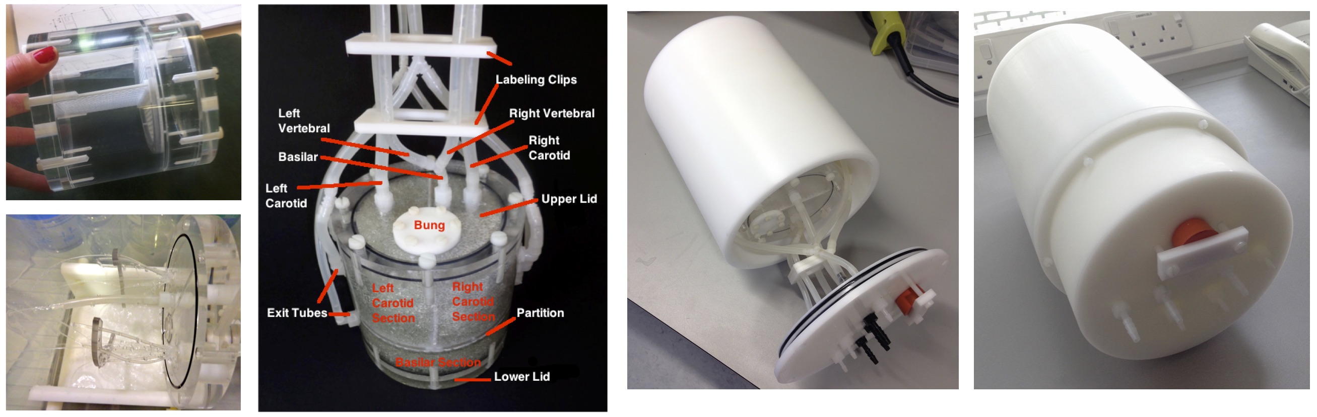
A three-territory flow phantom was built, as show in Fig. 1. It consisted of a cylinder which was divided into three chambers (left carotid, right carotid and vertebro-basilar) using a permeable divider, with a total volume of 785.4 mL. Four 'arteries' were created using 4.8 mm (carotid) and 3.2 mm (vertebral) internal diameter tubing. These were arranged in the labelling region in the form of a straight trapezium, with 35mm separation for the carotids and 25 mm for the vertebrals. The two vertebrals were fused after the labelling region into a single (basilar) tube which passed along the centre of the two carotid fed chambers to the basilar chamber. Outflow was captured at the periphery and returned to the inflow by way of a peristaltic pump. Gauze meshes were fitted at all outflows to prevent leakage of the chamber’s filling. The chamber was then housed in a cylindrical casing designed to fit into a standard MRI head coil.
Water was used as the perfusion medium and qualitative evaluation was performed on a number of different filling materials, to mimic perfusion type behaviour. The aim was to use a material that provided a (static) water content, to obtain a good signal-to-noise ratio and minimise field distortion, as well as provide suitable restriction to flow to mimic the process of perfusion when blood meets the capillary bed. Candidate filling materials included glass beads, sponge, hydrogel and super-absorbent polymer fillings including an alginate-(potassium acrylate) composite.
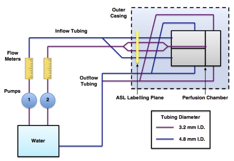
The device was placed in a continuous flow circuit as shown in Fig. 2. The phantom was imaged using multi post-labelling delay pcASL as well as a VE-pcASL acquisition5, for both cases bolus duration was 1400 ms and a range of post labelling delays from 250 ms to 1500 ms with interval 250 ms were used. The separation of signals arising from each feeding 'artery' in the VE-pcASL data was performed using a maximum a posteriori (MAP) solution to the general Bayesian framework6. Maps of perfusion and arterial transit time were evaluated from the multi PLD data using BASIL from FSL7.
Results
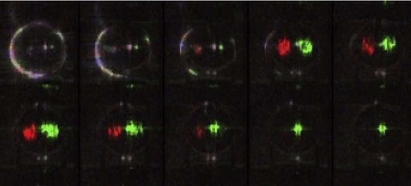
Fig. 3 shows a single slice from the 'carotid' chambers at a range of post-labelling delays with an overall flow rate of the phantom of 15.6 ml/s and sponge filling material. Signal from the delivery of labelled water from both 'arteries' could be seen and relative perfusion could be quantified. The sponge filling provided too great a restriction of flow to get an even perfusion effect across the chamber.
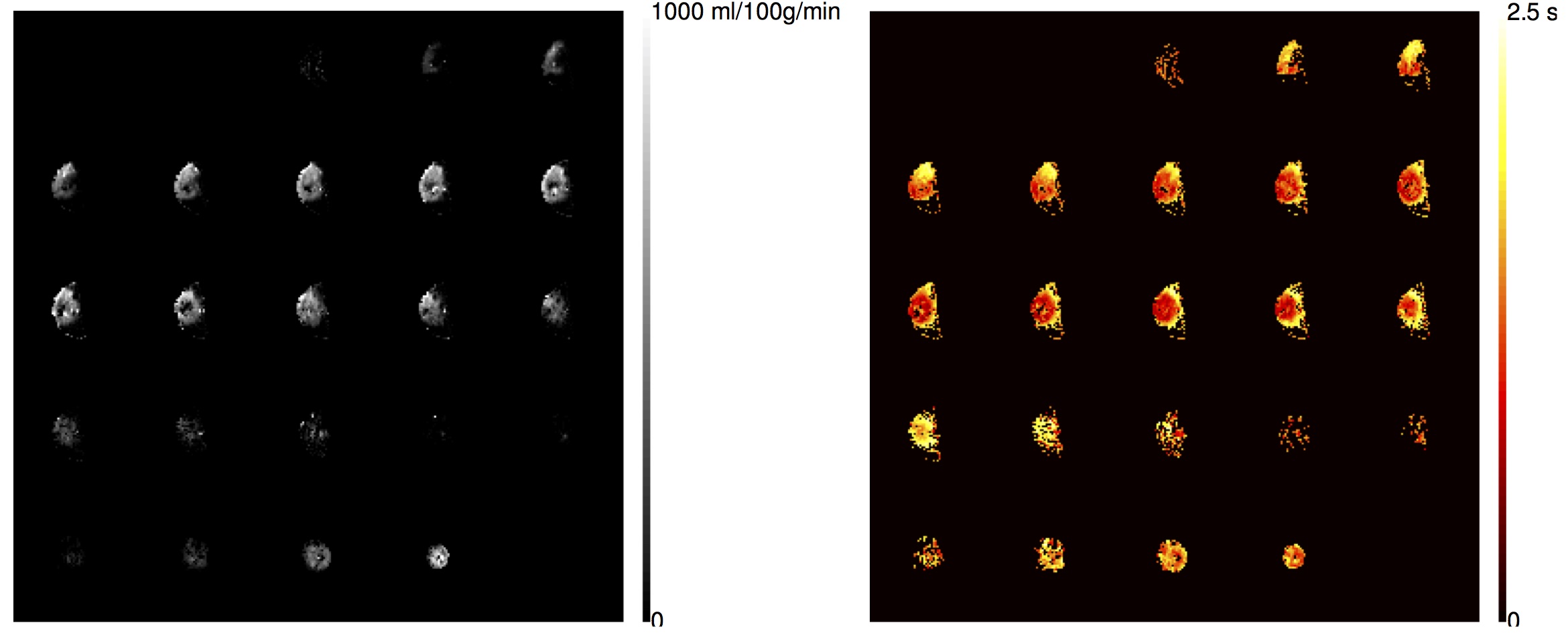
Fig. 4 shows slices through the all the chambers of total perfusion and arrival time, from pcASL, using a hydrogel filling material, in this experiment a blockage to the left 'carotid' tube resulted in reduced perfusion in that territory.
Discussion/Conclusion
Realistic geometries and flow rates were achieved for the arteries in the phantom allowing VE-ASL to be evaluated. Choosing the correct filling material to mimic perfusion was challenging and more work could be done. However, reasonable perfusion and arrival time images were obtained from pcASL and territorial images using VE-ASL. Although evaluated here for perfusion imaging, this device could also be used for evaluating an angiographic readout as well.Acknowledgements
The development of this device was generously supported by the Lubbock Trust.References
1. Oliver-Taylor, A Perfusion Phantom with Distinct Vascular Territories. Proc. Brit. Chap. ISMRM 2011.
2. Gold Standard Phantoms, https://www.goldstandardphantoms.com/asl-perfusion-phantom
3. Günther. Efficient visualization of vascular territories in the human brain by cycled arterial spin labeling MRI. Magn Reson Med 56:671–675, 2006.
4. Wong. Vessel-encoded arterial spin-labeling using pseudocontinuous tagging. Magn Reson Med 58:1086–1091, 2007.
5. Okell et al. Cerebral Blood Flow Quantification Using Vessel-Encoded Arterial Spin Labeling. J Cerebral Blood Flow and Metab 33:1716–24, 2013
6. Chappell et al. A fast analysis method for non-invasive imaging of blood flow in individual cerebral arteries using vessel-encoded arterial spin labelling angiography. Med Image Anal 16, 831–839, 2012.
7. www.fmrib.ox.ac.uk/fsl/basil
Figures