3350
Applied Gradient Nonlinearity Correction for Quantitative Diffusion MRI1Vanderbilt University Medical Center, Nashville, TN, United States, 2University of Texas at Austin, 3Mayo Clinic, 4Vanderbilt University
Synopsis
Accurate and reliable quantitative diffusion MRI depends on correcting for spatially varying errors in applied diffusion gradients due to nonlinearity of the gradient coil fields. We measured the temporal and inter-scanner variability of a phantom-based correction protocol on four different scanners. Estimated errors in diffusion gradient b-value and direction were significant, and differed between scanners. Scanner differences in temporal stability indicated the need for site-specific calibrations.
INTRODUCTION
Diffusion MRI has become a common tool for studying brain microstructure, and holds promise for providing important biomarkers in many clinical and neuroscientific contexts. However, several factors make it difficult to obtain quantitatively reliable diffusion measurements that are comparable across sites and scanners. One of these is gradient coil nonlinearity, which causes spatially varying errors in the applied diffusion gradients during diffusion-weighted MR imaging sequences. These errors are especially important in the context of multi-site studies [1]. The nonlinearity errors can be corrected using information about the actually applied gradient coil fields [2]. Such methodology has demonstrated significant improvements in accuracy and site-to-site comparability [3,4,5,6] and is becoming standard practice for large scale diffusion imaging studies [7,8]. Here we report on the temporal stability and site-to-site variation of a calibration method that uses gradient coil field maps measured with a large phantom to estimate the actual voxel-specific diffusion gradient amplitudes and directions applied during diffusion weighted imaging.METHODS
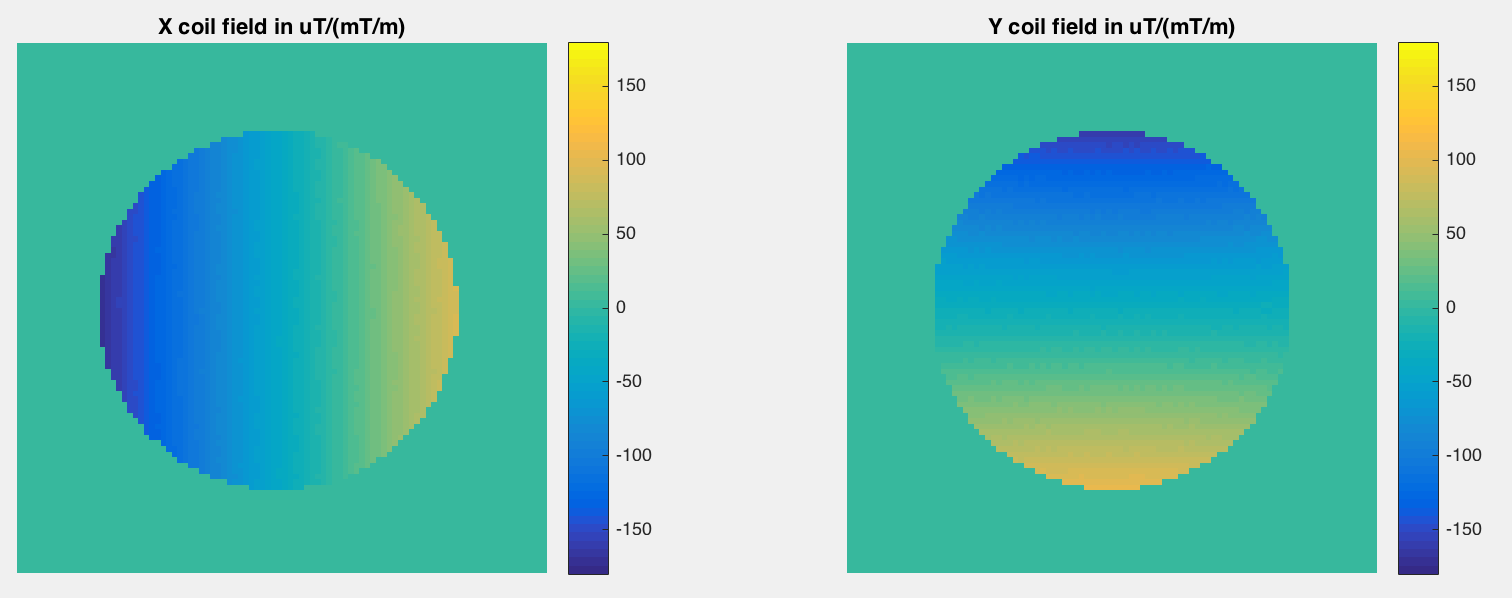
Gradient coil field mapping scans were performed on four 3 Tesla scanners from three major vendors. We used a synthetic white oil phantom of 290 mm diameter, placed at isocenter. Site-specific gradient echo field mapping sequences were used to measure the field of each linear gradient coil in a 384 mm field of view (Figure 1). For two of the scanners, field maps were made weekly over the course of four months.
For each calibration scan, a 5th order solid harmonic model [9,10] was fit to the field produced by each gradient coil using robust linear regression. Field measurements from all voxels within 125 mm of isocenter were used. Coefficients of the solid harmonic model were stored for each scan.
The achieved b-value and gradient direction for a specific intended diffusion gradient at a specific location may be computed as $$$b' {\bf g'} = {\bf L} b \bf{g}$$$ where $$$b$$$ is the intended b-value, $$${\bf g}$$$ is the intended gradient direction, $$$b'$$$ and $$${\bf g'}$$$ are the achieved gradient, and $$${\bf L}$$$ is the spatially varying tensor of spatial derivatives of the modeled field [2,3]. While approximate, this correction is easily applied when the full b-matrix [11,12] is not available. We applied the nonlinearity correction determined from the field maps to the intended b-values and gradient directions reported by each scanner, on a voxel-wise basis.
RESULTS
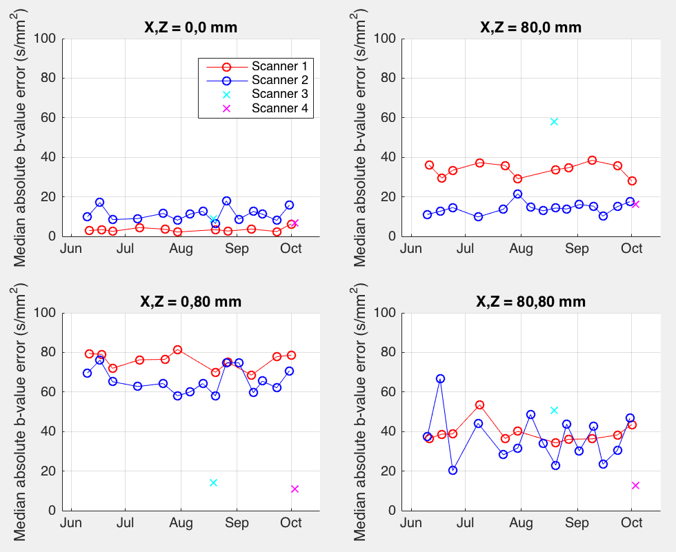
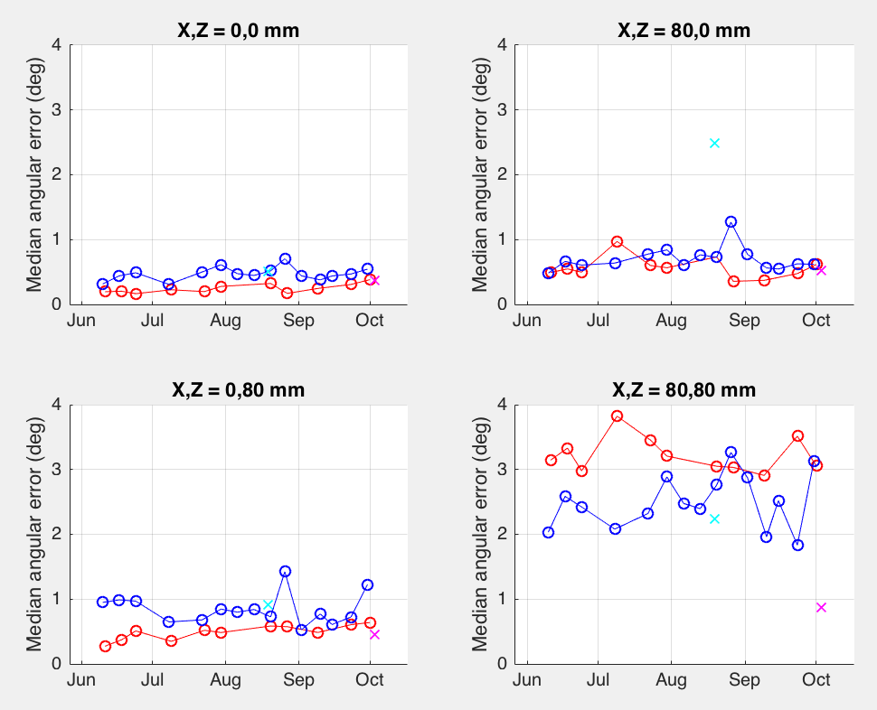
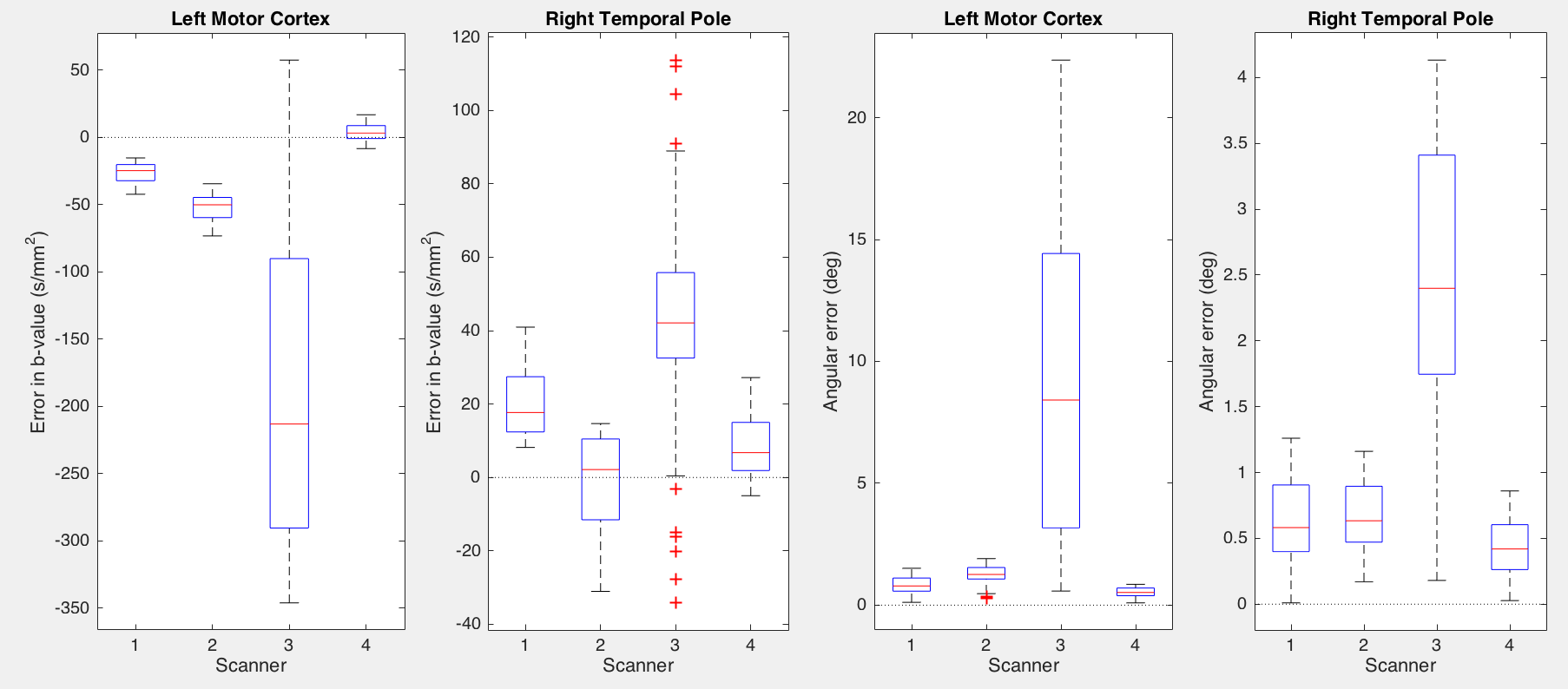
Estimated b-value error (median over all diffusion gradient directions) is shown in Figure 2. It was relatively small at scanner isocenter, ranging from 2 to 18 s/mm^2 across the four scanners. At positions 80 mm off axis, estimated median errors ranged from 10 to 81s/mm^2 . Stability of repeated measurements at the same scanner over time varied; scanner 1 showed a standard deviation of 5.3 s/mm^2, while scanner 2's standard deviation was 12.3 s/mm^2 for off-axis locations. Typical (median) angular errors in applied gradient direction showed a similar pattern (Figure 3) being 0.7 degrees at worst at isocenter, but ranging up to 3.8 degrees off axis. Standard deviations over time of angular error ranged from 0.07 degrees at isocenter to 0.23 degrees off axis (scanner 1) or 0.10 to 0.42 degrees (scanner 2). Different scanners exhibited their largest errors in different spatial locations, thus emphasizing the need for scanner-specific calibration.We additionally estimated the b-value and direction errors at specific anatomical locations in the brain of a volunteer who was scanned on all four scanners. This measurement incorporates variations in head placement as well as differences in scanner hardware and software. Corrections needed for a typical 96-direction diffusion sequence are shown in Figure 4. The amplitude, direction, and variability of the estimated errors differed considerably between scanners, with b-value errors ranging from 0 to 346 s/mm^2 and angular error ranging from 0 to 22 degrees.CONCLUSIONS
We observed gradient field nonlinearity large enough to cause important variations in b-value and gradient direction within a typical brain imaging field of view, confirming previous observations [1,2,4,13]. The effect must be corrected to improve site-to-site consistency in quantitative diffusion imaging. The proposed empirical correction procedure is based on a brief field map scan, can be performed retroactively, and has the promise to allow accurate correction of gradient nonlinearity effects within standard diffusion analysis pipelines. Stability of the measurement over time is scanner dependent, so the calibration procedure is likely to need to be optimized on a site-by-site basis.Acknowledgements
Supported by NIH (NIBIB) R01 EB017230-02 to Bennett A. Landman. This study was supported in part using the resources of the Advanced Computing Center for Research and Education (ACCRE) at Vanderbilt University, Nashville, TN. This project was supported in part by the National Center for Research Resources, Grant UL1 RR024975-01, and is now at the National Center for Advancing Translational Sciences, Grant 2 UL1 TR000445-06.References
[1] D. I. Malyarenko, D. Newitt, J. W. L et al., “Demonstration of nonlinearity bias in the measurement of the apparent diffusion coefficient in multicenter trials,” Magn Reson Med, 75(3), 1312-23 (2016).
[2] R. Bammer, M. Markl, A. Barnett et al., “Analysis and generalized correction of the effect of spatial gradient field distortions in diffusion-weighted imaging,” Magn Reson Med, 50(3), 560-9 (2003).
[3] E. T. Tan, L. Marinelli, Z. W. Slavens et al., “Improved correction for gradient nonlinearity effects in diffusion- weighted imaging,” J Magn Reson Imaging, 38(2), 448-53 (2013).
[4] D. C. Newitt, E. T. Tan, L. J. Wilmes et al., “Gradient nonlinearity correction to improve apparent diffusion coefficient accuracy and standardization in the american college of radiology imaging network 6698 breast cancer trial,” J Magn Reson Imaging, 42(4), 908-19 (2015).
[5] D. I. Malkyarenko, and T. L. Chenevert, “Practical estimate of gradient nonlinearity for implementation of apparent diffusion coefficient bias correction,” J Magn Reson Imaging, 40(6), 1487-95 (2014).
[6] D. I. Malyarenko, B. D. Ross, and T. L. Chenevert, “Analysis and correction of gradient nonlinearity bias in apparent diffusion coefficient measurements,” Magn Reson Med, 71(3), 1312-23 (2014).
[7] S. N. Sotiropoulos, S. Jbabdi, J. Xu et al., “Advances in diffusion MRI acquisition and processing in the Human Connectome Project,” Neuroimage, 80, 125-43 (2013).
[8] M. F. Glasser, S. N. Sotiropoulos, J. A. Wilson et al., “The minimal preprocessing pipelines for the Human Connectome Project,” Neuroimage, 80, 105-24 (2013).
[9] M. J. Caola, “Solid harmonics and their addition theorems,” J Phys A: Math Gen, 11(2), L23-L25 (1978).
[10] R. J. A. Tough, and A. J. Stone, “Properties of the regular and irregular solid harmonics,” J Phys A: Math Gen, 10(8), 1261-1269 (1977).
[11] J. Mattiello, P. J. Basser, and D. Le Bihan, “The b matrix in diffusion tensor echo-planar imaging,” Magn Reson Med, 37(2), 292-300 (1997).
[12] J. Mattiello, P. J. Basser, and D. LeBihan, “Analytical expressions for the b matrix in NMR diffusion imaging and spectroscopy,” J Magn Reson, Ser A, 108(2), 131-141 (1994).
[13] Y. C. Wu, and A. L. Alexander, “A method for calibrating diffusion gradients in diffusion tensor imaging,” J Comput Assist Tomogr, 31(6), 984-93 (2007).
Figures