3227
Comparison of 4D Flow MRI and Tomographic Particle Image Velocimetry1Mechanical Engineering, University of Wisconsin-Madison, Madison, WI, United States, 2Mechanical Engineering and Radiology Department, University of Wisconsin-Madison
Synopsis
4D flow MRI has shown promising results, assessing hemodynamics in different vascular territories. In order to keep expanding its clinical use, reliable validation of 4D flow MRI is needed for improvement of its accuracy and precision while reducing scan time. The purpose of this study was to compare velocity measurements through an in vitro carotid artery bifurcation model using 4D Flow MRI and particle image velocimetry. PIV system provides great insight into the velocity field within the model, using an excellent acquisition quality.
Purpose
4D flow MRI has shown promising results, assessing hemodynamics in different vascular territories. In order to keep expanding its clinical use, reliable validation of 4D flow MRI is needed for improvement of its accuracy and precision while reducing scan time. Velocity and flow measurements from 4D flow MRI have been previously validated with numerical simulations 1,2, and in vitro systems using 2D PC-MR 3 and Doppler ultrasound. More recent studies have used particle image velocimetry (PIV) to optically measure flow velocity using cameras that capture movement of particles illuminated by a laser 4,5,6. Stereoscopic PIV (Stereo-PIV), where the three velocity components (3C) are measure on a 2D plane, and tomographic PIV (Tomo-PIV), that uses three-dimensional cross-correlation to determine the corresponding 3D-3C velocity field 7, are common PIV variations. The purpose of this study was to compare velocity measurements through an in vitro carotid artery bifurcation model using 4D Flow MRI, Stereo-PIV and Tomo-PIV.Methods
MR Imaging: A silicone phantom of a carotid artery bifurcation was connected to a perfusion pump and scanned on a clinical 3T scanner (Discovery MR 750, GE Healthcare, Waukesha, WI), using a wrist coil. 4D flow MRI was performed with a 5-pt radial-undersampled technique, PC-VIPR 8. Imaging parameters were as follows: imaging volume: 24 x 24 x 24 cm; 0.625 mm acquired isotropic spatial resolution; TR/TE = 6.4/1.8 ms; VENC = 75 cm/s. MRI was performed while a solution of water and glycerol circulated through the model at 1 L/min. Gadofosveset trisodium (Ablavar, Lantheus Medical Imaging, N. Billerica, MA) was added to the solution to improve the signal to noise ratio.
4D Flow MRI Quantification: Vessel segmentation was performed in Mimics (Materialise, Leuven, Belgium), where a three‑dimensional (3D) geometry was generated from the PC angiogram. Visualization and quantification of 4D Flow MRI data was done in Ensight (CEI Inc., Apex, NC). Vorticity and kinetic energy were calculated from the measured velocity.
PIV Acquisition and Analysis: PIV was performed on the silicone phantom using a Flowmaster PIV system (LaVision, Göttingen, Germany). The system consisted on a dual-pulse 527 nm Nd:YLF laser perpendicular to two high speed cameras Phantom v341. A solution, seeded with polymer particles (diameter = 10 mm), of 28.0% glycerol, 56.1% water and 15.9% sodium iodide was pumped at 1 L/min through the model to match its refractive index (n = 1.41). The system acquired 100 sets of images (25 mm pixel size) at a frame rate of 402 Hz. The time separation between images on each set was 300 ms yielding a maximum particle displacement of 125 mm in the center of the vessel. Data were analyzed in Ensight where vorticity and kinetic energy were calculated using the measured velocity.
Results
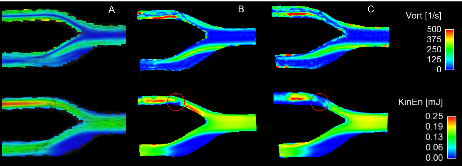
Good agreement of vorticity and kinetic energy calculations was observed between 4D flow MRI, Stereo-PIV and Tomo-PIV (Fig2). 2D planes were extracted from 4D flow MRI and Tomo-PIV, in order to compare the results to those from Stereo-PIV. Figure 3, shows a direct comparison between 4D flow MRI and Tomo-PIV revealing good agreement.Discussion
Peak velocities as well as a recirculation (stagnant flow) region were found downstream of the bifurcation using the three methods. Better agreement was found between Tomo-PIV and 4D flow MRI when comparing vorticity, suggesting the presence of higher out-of-plane velocities in Tomo-PIV, not detected by Stereo-PIV. The use of Stereo-PIV in multiple planes will potentially improve its agreement with the other two methods by creating a 3D flow field. Non-illuminated area was obtained (red circles in Figure 2) in the upper branch of the bifurcation, affecting the comparison between techniques in that area. However, lower branch and main vessel results allowed the comparison of the three techniques.Conclusion
PIV system provides great insight into the velocity field within the model, using an excellent acquisition quality. Stereo-PIV results demonstrated to be a faster and easier technique to measure 3C velocity field. On the other hand, Tomo-PIV can take longer to calibrate and post-process but results reveal excellent agreement with 4D flow MRI. Further analysis of the PIV results will allow us to evaluate different flow regimes such as turbulent flow and the boundary layer, not possible with MRI due to the limited temporal and spatial resolution.Acknowledgements
We acknowledge support from the AHA (14SDG19690010), UW Radiology R&D and GE Healthcare.References
1. Roldán-Alzate, A., et al. Hemodynamic study of TCPC using in vivo and in vitro 4D Flow MRI and numerical simulation. J. Biomech. 2015; 48, 1325–1330
2. Jiang, J., et al. Flow characteristics in a canine aneurysm model: a comparison of 4D accelerated phase-contrast MR measurements and computational fluid dynamics simulations. Med. Phys. 2011; 38, 6300–12.
3. Carlsson, M., et al. Quantification and visualization of cardiovascular 4D velocity mapping accelerated with parallel imaging or k-t BLAST: head to head comparison and validation at 1.5 T and 3 T. J. Cardi MR. 2011; 13:55
4. Töger, J., et al. Independent validation of four-dimensional flow MR velocities and vortex ring volume using particle imaging velocimetry and planar Laser-Induced fluorescence. Magn. Reson. Med. 2016; 75, 1064–1075.
5. Khodarahmi, I., et al. In vitro validation of flow measurement with phase contrast MRI at 3 tesla using stereoscopic particle image velocimetry and stereoscopic particle image velocimetry. J. Magn. 2014; 1485, 1477–1485.
6. Kitajima, H.D., et al. Comparison of particle image velocimetry and phase contrast MRI in a patient-specific extracardiac total cavopulmonary connection. J. Biomech. Eng. 2008; 130, 41004.
7. Buchmann, N.A., et al. 2011. Tomographic particle image velocimetry investigation of the flow in a modeled human carotid artery bifurcation. Exp. Fluids. 2011; 50, 1131–1151.
8. Johnson, K.M., Markl, M. Improved SNR in phase contrast velocimetry with five-point balanced flow encoding. Magn. Reson. Med. 2010; 63, 349–355.
Figures
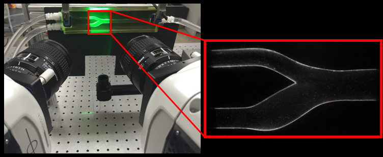
Figure 1. PIV system. A laser pulse is synchronized with cameras to illuminate fluorescent particles. Images from two high-speed cameras are simultaneously acquired to track the fluid flow.