3188
Hepatic MR Elastography (MRE) System Longitudinal Quality Assurance (QA) Protocol1Radiology, Mayo Clinic, Rochester, MN, United States
Synopsis
A suitable quality assurance (QA) phantom and image acquisition and processing procedures were developed for confirming the proper function and longitudinal stability of these MRE systems. The goals of this educational poster are to demonstrate the QA phantom, the longitudinal testing protocol, and the utility of detecting a problem caused by discontinuous motion.
Background
To date, commercially available, FDA-cleared, MR Elastography (MRE) systems have been installed on approximately 800 MRI units around the world for clinical applications and research activities. The major subsystems required to perform hepatic MRE are 1) an acoustic driver device to generate vibrations in the liver, 2) an imaging sequence capable of recording the tissue vibrations into the phase of MR images (“wave images”), and 3) an algorithm to process the wave images to generate images of tissue elasticity (“elastograms”). While the imaging sequence and inversion algorithm subsystems do not change once installed, human error and hardware problems can prevent motion from being produced or can cause discontinuous motion in the acoustic driver subsystem, which alters the measured wave information in ways that can corrupt the elastograms. We have developed a suitable quality assurance (QA) phantom and image acquisition and processing procedures for confirming the proper function and longitudinal stability of these MRE systems. The goals of this educational poster are to demonstrate the QA phantom, the longitudinal testing protocol, and the utility of detecting a problem caused by discontinuous motion.Method: QA Protocol
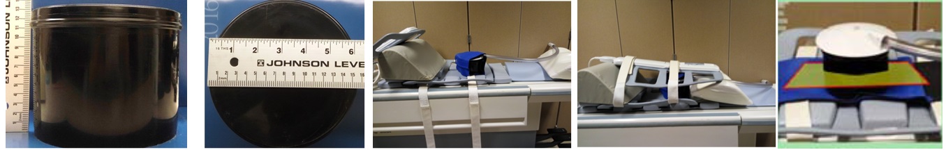
Phantom Setup: The MRE QA phantom is made of Polyvinyl Chloride (PVC) in a 12.5-cm high,15.5-cm diameter cylinder container with a lid (Figure 1). The MRE QA phantom setup uses a standard patient liver MRE passive driver, the standard elastic belt used to secure the driver to the patient, a phantom-specific friction cloth to prevent slipping between the driver and the phantom, and a standard torso RF coil array (Figure 1).
Imaging Parameters: The phantom imaging parameters have been optimized for GE, Siemens and Philips MRI systems according to the phantom relaxation times, chemical spectrum and geometry. The imaging parameters for each vendor are available upon request. For example, on a 1.5-T whole-body MR imaging system (GE Signa HDxt, GE Healthcare, Waukesha, WI), the imaging parameters of the GRE MRE sequence is as follows: coronal imaging, slice thickness = 10 mm, FOV = 20 cm, acquisition matrix = 256x64, TE = 18.6 ms, TR = 50 ms, flip angle = 25º, bandwidth = 31.25 kHz, parallel imaging acceleration factor = 1, choose the middle peak of the spectrum during prescan, MRE active driver power = 10%, driver frequency = 60 Hz, driver cycles = 3, motion-encoding-gradient (MEG) frequency = 75 Hz, MEG amplitude = 3 G/cm, 4 MRE time points, and MEG direction = through plane (Z).
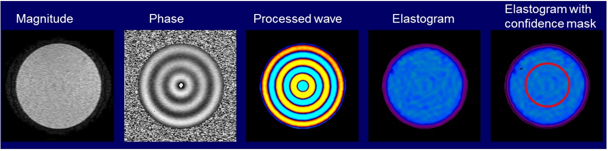
Region of Interest (ROI): Use the MRE MR magnitude image to define a circular ROI in the middle of the phantom with a diameter half that of the phantom’s diameter. The edges of the phantom should be avoided due to edge artifacts in the MRE image processing (Figure 2). The mean and standard deviation of the pixel values in the ROI on elastograms are reported as the phantom stiffness (typically in units of Pa or kPa).
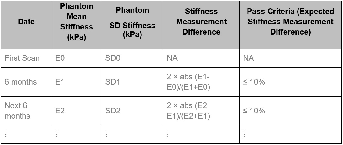
Longitudinal Schedule and Pass Criteria: The MRE QA phantom exams should be scheduled every six months for each site. The longitudinal pass criterion uses the difference in the measured stiffness at two consecutive time points (Figure 3). The pass criterion for the current exam is a stiffness measurement difference ≤ 10%. The threshold of 10% is used to account for the possibility of the PVC phantom stiffening over time (up to 10% per year).
Example of Failed MRE QA Exam
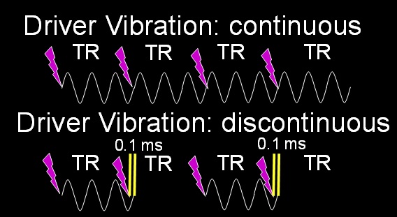
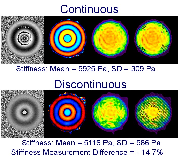
During hepatic MRE scans, the driver motion is required to be continuous because discontinuous motion can cause errors in the elastograms. Motion discontinuities normally happen when the duration of the active driver is shorter or longer than the TR of the imaging sequence. Usually the motion duration and TR are precalculated and synchronized so the motion is always continuous. However, if the TR and the driver duration are inadvertently set to incorrect values, then the synchronization between the MRE hardware and the imaging sequence can be disrupted, causing the vibrational motion to be discontinuous. We demonstrate a failure situation in which we intentionally set the motion duration 0.1 ms longer than the TR (50 ms) so the synchronizing triggers from the imaging sequence are missed every other TR causing motion discontinuity (Figure 4). In a 5.9 kPa PVC phantom, this discontinuity caused a stiffness measurement difference of -14.7%, which did not meet the pass criterion (Figure 5).Conclusion
A MRE system longitudinal QA protocol is key to verifying the integrity of the whole hepatic MRE system over time and insuring that the MRE system is working properly. This is critical when using MRE to longitudinally monitor liver disease progression or treatment efficacy.Acknowledgements
NIH EB 001981References
No reference found.Figures