2856
MRI-based Fluid Structure Interaction Simulation of the Bicuspid Aortic Valve using Native Non-linear Valve Properties1Radiology, Northwestern University, Chicago, IL, United States, 2Saint Anthony Falls Laboratory, University of Minnesota Minneapolis, MN, United States, 3Department of Civil,Environmental and Geo-engineering, University of Minnesota Minneapolis, 4Stony Brook University
Synopsis
Limitations of temporal and spatial resolution prevent MRI from visualizing boundary layers and fluid structure interaction (FSI) occurring immediately adjacent to the valve leaflets as well as at the aortic wall downstream from the valve. We make use of CMR image-based patient specific anatomy and boundary conditions to perform computational fluid dynamic (CFD) analysis which incorporates moving boundary conditions. The numerical approach is shown to elucidate complex and dynamic blood and leaflet behavior previously not seen with CMR alone.
Purpose
The bicuspid aortic valve (BAV) has attracted significant attention due to controversy surrounding whether genetics or hemodynamics are associated with concomitant aortopathy. Given that 4D flow MRI can simultaneously measure complex 3D anatomy and blood flow patterns, it is an ideal modality to investigate the hemodynamic hypothesis for aortopathy1, 2. Nonetheless, limitations of temporal and spatial resolution prevent MRI from visualizing boundary layers and fluid structure interaction (FSI) occurring immediately adjacent to the valve leaflets as well as at the aortic wall downstream from the valve. Increasing computational power combined with image-based patient specific anatomy and boundary conditions (available from MRI) has enabled reliable computational fluid dynamic (CFD) approaches which incorporate moving boundary conditions via FSI3, 4. These numerical approaches have the potential to elucidate complex and dynamic blood and leaflet behavior previously not seen with imaging alone.Methods
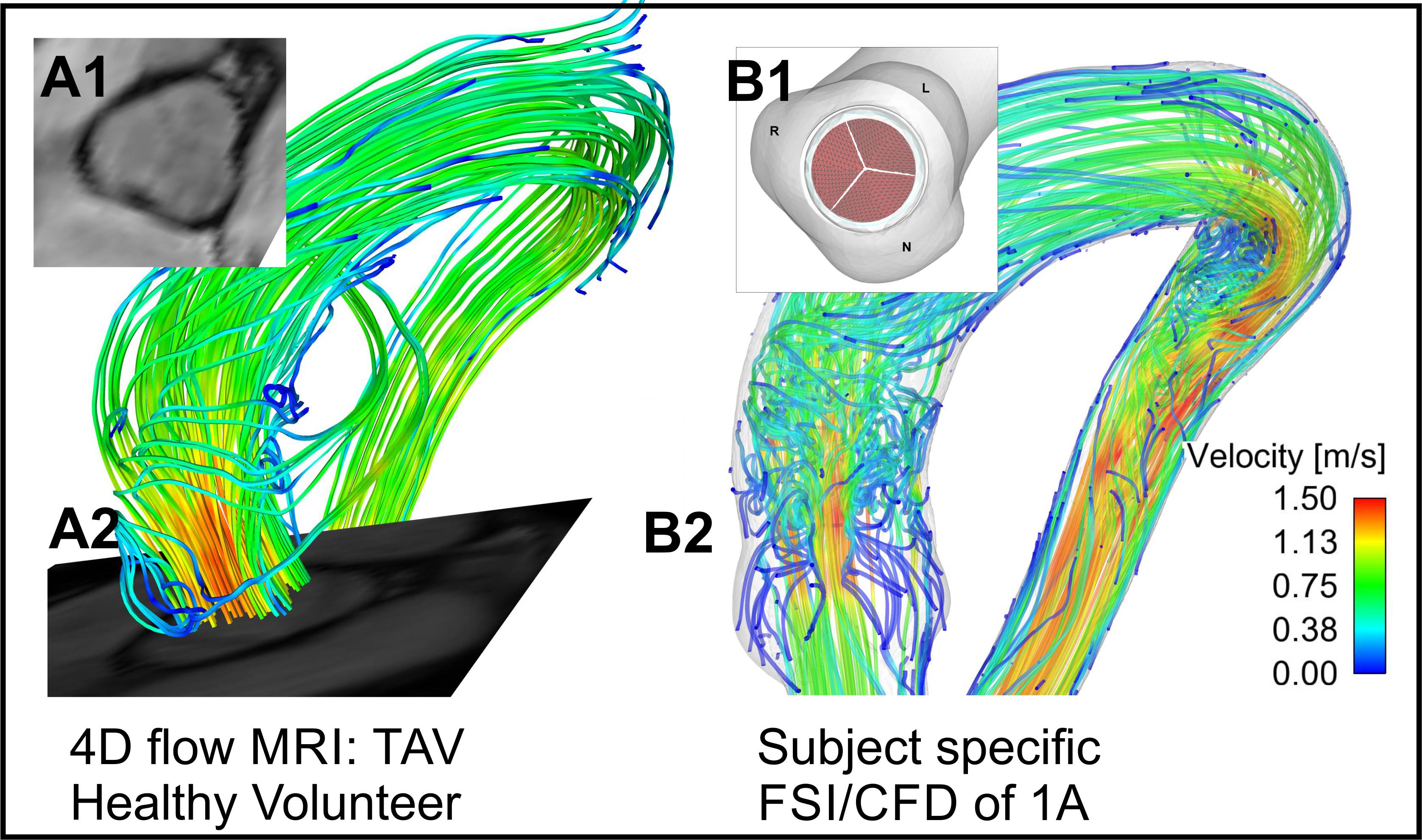
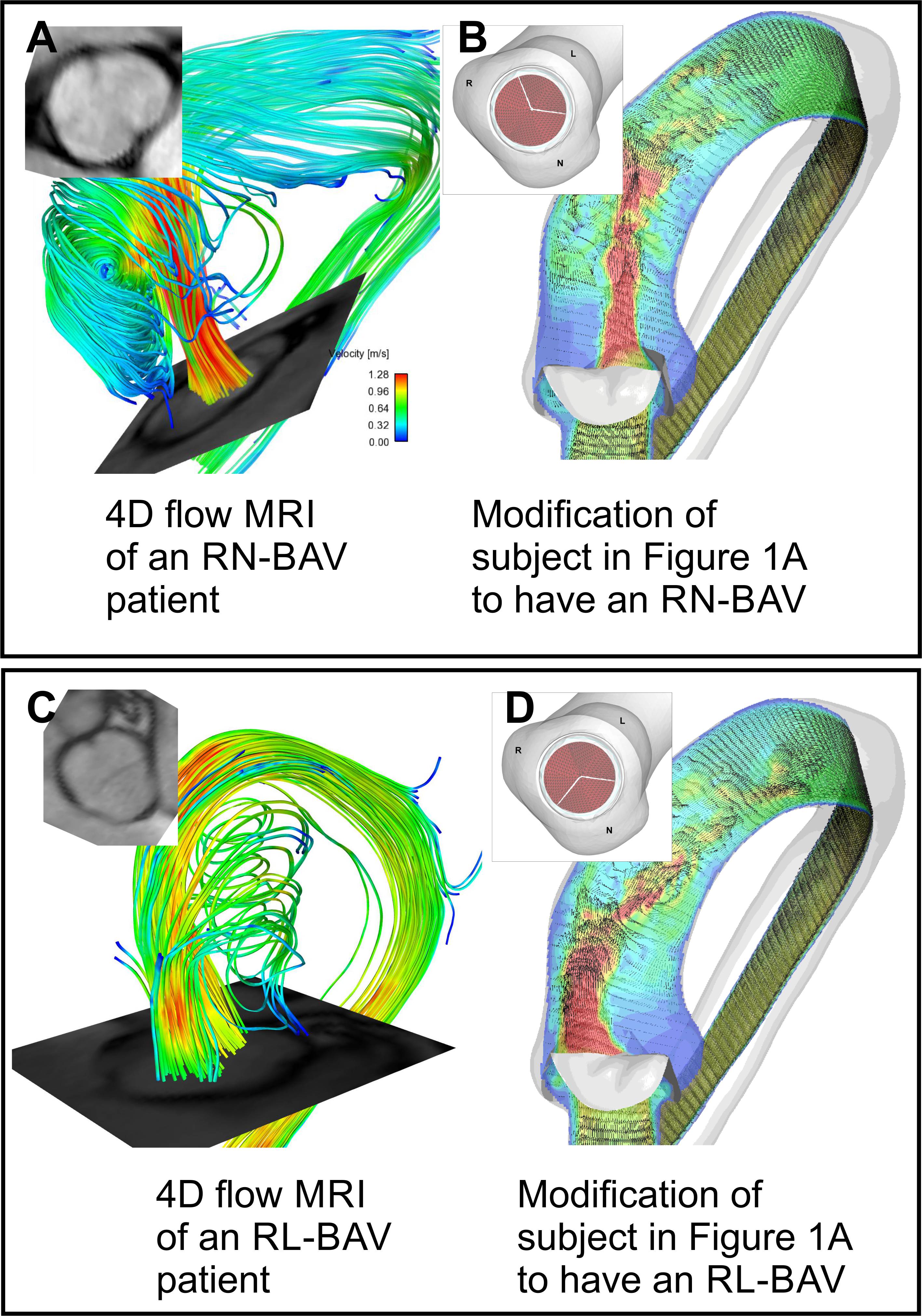
4D flow MRI and standard bSSFP cine imaging was performed in a healthy volunteer with no history of cardiovascular disease and a normal trileaflet aortic valve (TAV). Additionally, two patients with a confirmed suspected right-left coronary cusp fusion (RL-BAV) and a right-noncoronary cusp fusion (RN-BAV) underwent CMR, including 4D flow MRI and bSSFP cine imaging. The morphology of the valves was confirmed using cine images. The aorta of the healthy subject was subsequently segmented in 3D to facilitate the FSI/CFD simulations. Additionally, 3 valves models were created to replicate the morphology of the TAV, RN-BAV, and RL-BAV valves, as determined from the corresponding bSSFP images (insets, Figure 1-2). A Curvilinear Immersed Boundary Finite Element Fluid Structure Interaction (CURVIB-FE-FSI) method5 was employed. The leaflets of the aortic valve are modelled as a thin shell using the a rotational free FE formulationof6. A nonlinear anisotropic constitutive model of an aortic valve7, 8 was used to describe the native tissue of the heart valve. All valve simulations were performed using the geometry of the healthy aorta. A flow waveform created from the MRI flow velocities was used as the inlet the flow conditions for all models.Results
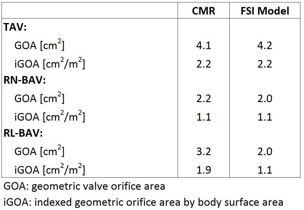
Figure 1A shows the MRI data from the healthy volunteer with normal TAV morphology. A comparison of the flow patterns to the FSI model is shown in Figure 1B (valve is not shown in Figure 1 B2 for clarity). Figure 2B & D shows parametric alterations to the healthy volunteer in order to mimic a RL-BAV and RN-BAV valve morphology. The flow patterns in the aorta between the two valve morphotypes are characterized by markedly different transvalvular jets. The outflow jets are indicative of those seen to increase wall shear stress in the proximal outer curvature of the RL-BAV model and more distal in the RN-BAV model. Similar patterns are seen for the patient MRI scans, even given the different left ventricular outflow tract and aortic geometry (Figure 2A & C). Of note, the geometric orifice area (GOA) and indexed orifice areas (iGOA) were similar between the model and CMR for the TAV and RN-BAV patient (Table 1). Differences were found between the model and CMR for the RL-BAV patient, which may explain the presence of lower transvalvular velocities in the CMR renderings as compared the FSI model (Figure 2C-D).Discussion
Blood flow patterns (such as the magnitude of flow velocities and the forces exerted on the aorta wall) are important factors leading endothelial mechanotransduction and maladaptive extracellular matrix remodeling. These mechanisms are strongly dependent on the action of the heart valve, and its intrinsic properties. Thus, we set out to develop realistic FSI simulations of aortic cusp motion and its downstream effects on blood flow in the aorta. The combination of two approaches allows for parametric variation and simulation of interventions. An example of parametric variation is shown by altering the valve morphologies in the healthy patient to mimic the flow behaviors seen in two valve phenotypes observed in BAV patients. Additionally, modifications can be made to simulate intrinsic changes to the biologic properties of the valve tissue (due to disease or aging), such as in the case of aortic stenosis.Acknowledgements
* Authors with asterisk contributed equally to this proceeding. Research reported in this publication was in part supported in part by the National Heart, Lung, And Blood Institute of the National Institutes of Health under Award Number K25HL119608.References
[1] Mahadevia, R, et al. Circulation, 2014. 129(6): p. 673-82.
[2] Guzzardi, DG, et al. Journal of the American College of Cardiology, 2015. 66(8): p. 892-900.
[3] Chandran, KB. Cardiovasc Eng Technol, 2010. 1(1): p. 18-38.
[4] Sotiropoulos, F, et al. Progress in Aerospace Sciences, 2014. 65: p. 1-21.
[5] Gilmanov, A, et al. J. Comput. Phys., 2015. 300(C): p. 814-843.
[6] Stolarski, H, et al. International Journal for Numerical Methods in Engineering, 2013. 95(9): p. 740-770.
[7] May-Newman, K, et al. Journal of Biomechanical Engineering, 1998. 120(1): p. 38-47.
[8] Gilmanov, A, et al. Journal of Biomechanics, 2016 (in press).
Figures