2765
A Cost-effective 3D Printed Cardiac MR Phantom1Medical Imaging Research Centre, Dayananda Sagar Institutions, Bangalore, India, 2Wipro-GE, Bangalore, India, 3Embedded Systems, Dayananda Sagar University, Bangalore
Synopsis
Cardiac phantoms have been employed as testing and validating tools for newly developed techniques focused on sampling and reconstruction strategies. In this work, a 3D printed cardiac phantom was built to mimic the human heart. This was achieved through the integration of a peristaltic pump. Results depict the structural and functional behavior of the cardiac phantom, based on MR imaging on 1.5T scanners from 2 vendors. Ongoing work involves implementing the post-processing pipeline to correlate UI parameters with those derived from images. Future work focuses on employing PVA for preparing the heart model employing the 3D printing heart mold.
Introduction
Cardiac phantoms have been employed as testing and validating tools for newly developed techniques focused on sampling and reconstruction strategies1,2. The cardiac MR phantom developed in this work aims to meet the following three objectives: (i) anatomically accurate representation of the human heart with potential for subject specific phantom imaging through 3D printed heart model (ii) MR characterisation of structural and functional behaviour of human heart (iii) Cost-effective, reproducible and repeatable phantom setup at lab scale.Materials and Methods
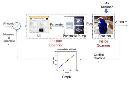
Cardiac Phantom setup: The setup consisted of a laptop, peristaltic pump (Ravel Hiteks Pvt Ltd) and a 3D printed cardiac model3. The laptop was connected to the pump and to the model through silicon pipes as shown in figure 1. One end of the pipe was connected to aortic arc and other end of the pipe was connected to left pulmonary artery. The laptop interfaced with the pump through a designed User Interface developed in Matlab (The Mathworks Inc). The UI inputs were clinically relevant parameters such as beats per minute (BPM), stroke volume (SV), cardiac output (CO) and acquisition time. These determined the pump parameters of flow rate, forward time, reverse time and number of cycles. UI outputs included BPM, volume, aortic flow, Left ventricular volume, Myocardial thickness and stress/strain as determined by MR images. The peristaltic pump was controlled to mimic the systolic and diastolic cycles. The calibration equations employed between the input and pump parameters are as shown in the equations below:
$$\alpha = \frac{60}{BPM}$$
$$pump forward time=\left(\frac{\alpha}{2}\right)\times 1000$$
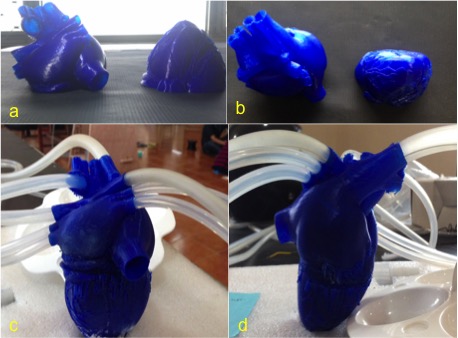
The cardiac heart model was printed with ninjaflex material with the extruder temperature maintained at 2100c and base plate temperature at 700c from an open source 3D printable model (3). Kapton tape was utilized to cover the bed to maintain the bed temperature. The heart was printed in two halves. The first half included the upper part of the phantom (from aorta to the tricuspid valve). The second half included the lower part of the heart (ventricles to apex of the heart). The two-part printing was performed to remove unnecessary supporting material. Figure 2 shows the two-part phantom and the attached pipes. Any remaining support material of phantom was then scrubbed off. The two halves were attached using waterproof glue and made leak-proof.
1.5T imaging: The 3D printed cardiac phantom was placed in a cylindrical plastic container filled with tap water. The pump was placed in the adjacent room to that of scanner room and scanned on 2 1.5T scanners from 2 different vendors. SSFP sequence was employed for scanning the phantom. The acquisition parameters on the first scanner were: TR/TE=4.0/1.72ms, FA=20, slice thickness=8, matrix size= 256 x 256. The acquisition parameters on second scanner were: TR/TE=50.8/1.4, FA=64, slice thickness=6, matrix size= 192 x 156.
Results
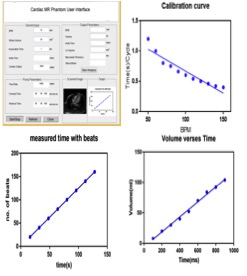
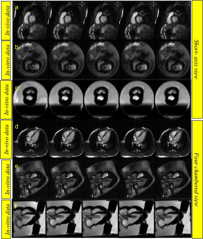
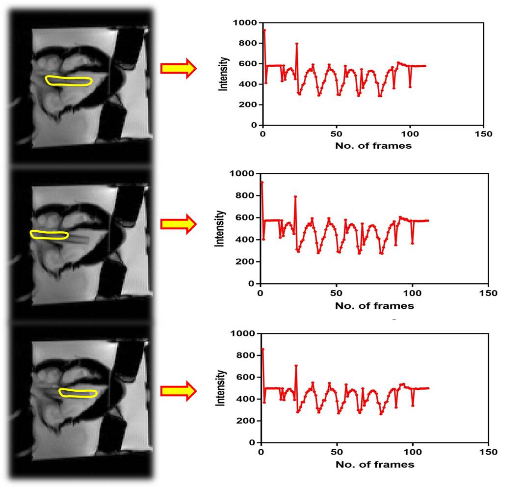
Figure 2 (a) shows the designed UI with panels for clinical parameters and pump related input calculations. Figure 2 (b) illustrates that increase in BPM decreases time per cycle as expected. Figure 2 (c) depicts that time increases with increase in number of beats while Figure 2 (d) shows that water volume increases linearly with as the pumping time as expected. The two different views of the 3D printed heart model can be seen in figure 3 (a,b). Figure 3 (c,d) exhibit the glued 3D heart model and the connected pipes for pumping in the water. The yellow arrow points to the position of the sponge used as phantom support, during scanning. The cine- MR images of cardiac in-vivo and in-vitro phantom data are shown in figure 4. Pipes inserted inside the two ventricles are visible in in-vitro data as two circular structures. The sinusoidal trend in the intensity plotted for cardiac-CINE demonstrates that the cardiac motion is mimicked during the scan as shown in figure 5.Discussion and Conclusion
Pipes were inserted deeper into the ventricles to allow suction of water as required by peristaltic pump for stable operation. The pipes inserted can be seen in the short – axis and four-chamber view of the in-vitro cardiac phantom in figure 4. Previous work carried out in [4] made use of polyvinyl alcohol (PVA) as phantom material. Current work involves implementing the post-processing pipeline to correlate UI parameters with those derived from images. Future work focuses on employing PVA for preparing the heart model employing the 3D printing heart mold. The phantom developed here could also be employed to study the fetal heart.Acknowledgements
1. This work was supported by Vision Group on Science and Technology (VGST), Govt. of Karnataka, Karnataka Fund for strengthening infrastructure(K-FIST), GRD#333/2015
2. Department of Science and Technology (DST), Govt. of India under the program Technology Systems Development (TSD) for the project “Novel acquisition and reconstruction strategies to accelerate magnetic resonance imaging using compressed sensing”, No: DST/TSG/NTS/2013/100-G.
3. Department of Information Technology (DIT), Govt. of India for the project "Indigenous - Magnetic Resonance Imaging (I-MRI)- A national Mission"
References
1. M. Ersoy “ A left Ventricular Motion Phantom for cardiac MRI” ISMRM 2011
2. Wissmann, L., Santelli, C., Segars, W. P., & Kozerke, S. (2014). MRXCAT: Realistic numerical phantoms for cardiovascular magnetic resonance. Journal of Cardiovascular Magnetic Resonance, 16(1), 6
3. http://doi.org/10.1186/s12968-014-0063-3 3. http://www.thingiverse.com/thing:852939
4. Chikop et al, "A Low cost Cardiac Phantom for Evaluation of Motion and Thermometry " ISMRM 2016
Figures