2715
Wrist coil for low field MRI1Medical Imaging Research Cenre, Dayananda Sagar Institutions, Bangalore, India
Synopsis
Image Signal to Noise Ratio (SNR) and resolution are significant challenges in ultra-low field MRI. A single channel transmit coil and a 4-channel phased array was developed for wrist to operate at 9.5mT. The current work involves integration with the DDS module for verifying functionality. Future work is to develop phased array for head MRI.
Purpose
Image Signal to Noise Ratio
(SNR) and resolution are significant challenges in ultra-low field MRI.
However, evaluation of the benefits of low field brain 1, 2 and
wrist MR3 is an area of active exploration. In this work, phased
array coils were used to demonstrate efficient B1- field
and SNR gain for the proposed application of wrist imaging at 9.5mT.Methods
Transmitter chain The complete schematic of Tx-Rx chain has been shown in figure 1. The Arduino Uno controlled Direct Digital Synthesis module was utilized for producing a pure sine wave at 405 kHz. Pulsing of this RF wave was achieved through programming using the Arduino IDE. This sinusoid was then fed to a well-tuned solenoid transmitter coil, via an RF amplifier. The solenoid coil of 11cm diameter was constructed by winding copper wire on PVC pipe. Inductance of the coil was 866.4µH, which along with tuning and matching capacitances of 121.1pF and 142.5pF respectively provides resonance at 405 kHz with a quality factor of 14. KEYSIGHT ENA Network Analyzer E5063A was used to measure Q. To avoid impedance mismatch, baluns were placed before and after the RF amplifier. The balun design is depicted in figure 2. An RF amplifier of 5 watts, which works on 12V/1A with amplification of 37dB was used. Wristband design The cylindrical, wearable wristband of 7.5cm diameter with well-defined geometrical structure was designed using Autodesk123D. This design configuration was imported to Simplify3D software to generate STL file for 3D printing. The generated STL file was uploaded in the J robotics 3-D printer. The Ninja semi flexible material was used for printing the cylindrical band. Receiver Coil design A four channel receiver coil at 405 kHz was constructed. These coil elements were placed on a cylindrical shaped wearable-flexible band around the wrist. Copper wire of 18 SWG gauge with three turns of 35mm diameter was chosen to increase the sensitivity, gain of the coil and geometrical design constraint of wristband. Tuning and matching resonant circuits were shielded with copper tape to avoid RF interference as shown in the figure 3A. Resistance and impedance of the coil was calculated per length for that gauge using LCR meter. Each coil was individually connected to a low noise LT1007 amplifier, operating with gain 10, to obtain an amplified received signal at 405 kHz. Coil placement and characterization Coil elements were placed on 3D printed wearable flexible band, forming the cylindrical shaped wrist band. Fully assembled coil array provides comfort to the wrist due to the ninja wearable flexible material as shown in the figure 4A. Each coil element had tuning/matching circuitry. Network analyzer was utilized for determining S21 and S11Results
A power reflection from the RF amplifier to the relay added noise to sinusoidal signal generated by the DDS. A balun was added to reduce this reflection between RF amplifier and DDS. The measured S21 between one coil and its nearest neighbor coil has been depicted in figure 3B. Coupling was observed between the channels and was measured using S21 measurement. The measured S21 ranges from -10dB to -23dB with a quality factor of 14 for each coil. The measurement of S21 has been shown in figure 4B.Conclusion
A single channel transmit coil and a 4-channel phased array was developed for wrist to operate at 9.5mT. The current work involves integration with the DDS module for verifying functionality. Future work is to develop phased array for head MRI.Acknowledgements
1.This work was supported by Vision Group on Science and Technology (VGST), Govt. of Karnataka, Karnataka Fund for strengthening infrastructure(K-FIST), GRD#333/2015
2.Department of Information Technology (DIT), Govt. of India for the project "Indigenous - Magnetic Resonance Imaging (I-MRI)- A national Mission"
References
[1] Sarracanie M, LaPierre CD, Salameh N, Waddington DEJ, Witzel T, Rosen MS. Low-cost High-Performance MRI. Scientific Reports. 2015;5:15177. doi:10.1038/srep15177.
[2] Cooley C, Stockmann JP, Armstrong BD, et al. 2D Imaging in a Lightweight Portable MRI Scanner without Gradient coil. Magnetic resonace in medical: official journal of the society of Magnetic Resonance in Medical/Society of Magnetic Resonance in Medicine.2015;73(2):872-883. Doi:10.1002/mrm.25147
[3] I. Savukov, T. Karaulanov, C.J.V. Wurden, L. Schultz, Non-cryogenic ultra-low field MRI of wrist–forearm area, Journal of Magnetic Resonance, Volume 233, August 2013, Pages 103-106, ISSN 1090-7807, http://dx.doi.org/10.1016/j.jmr.2013.05.012.
Figures
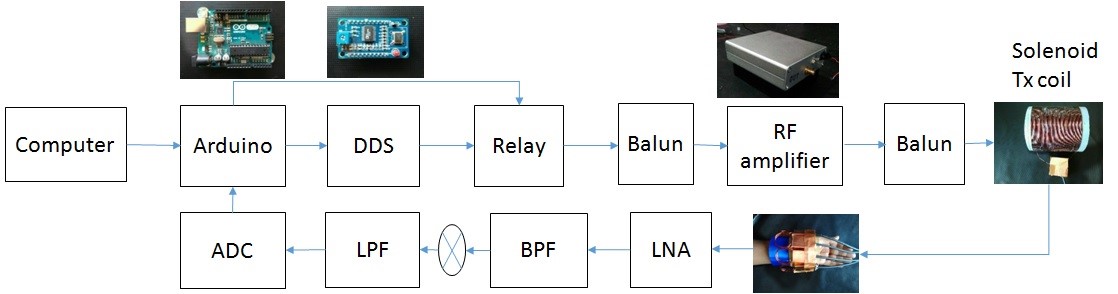
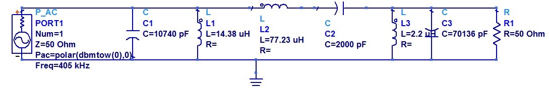
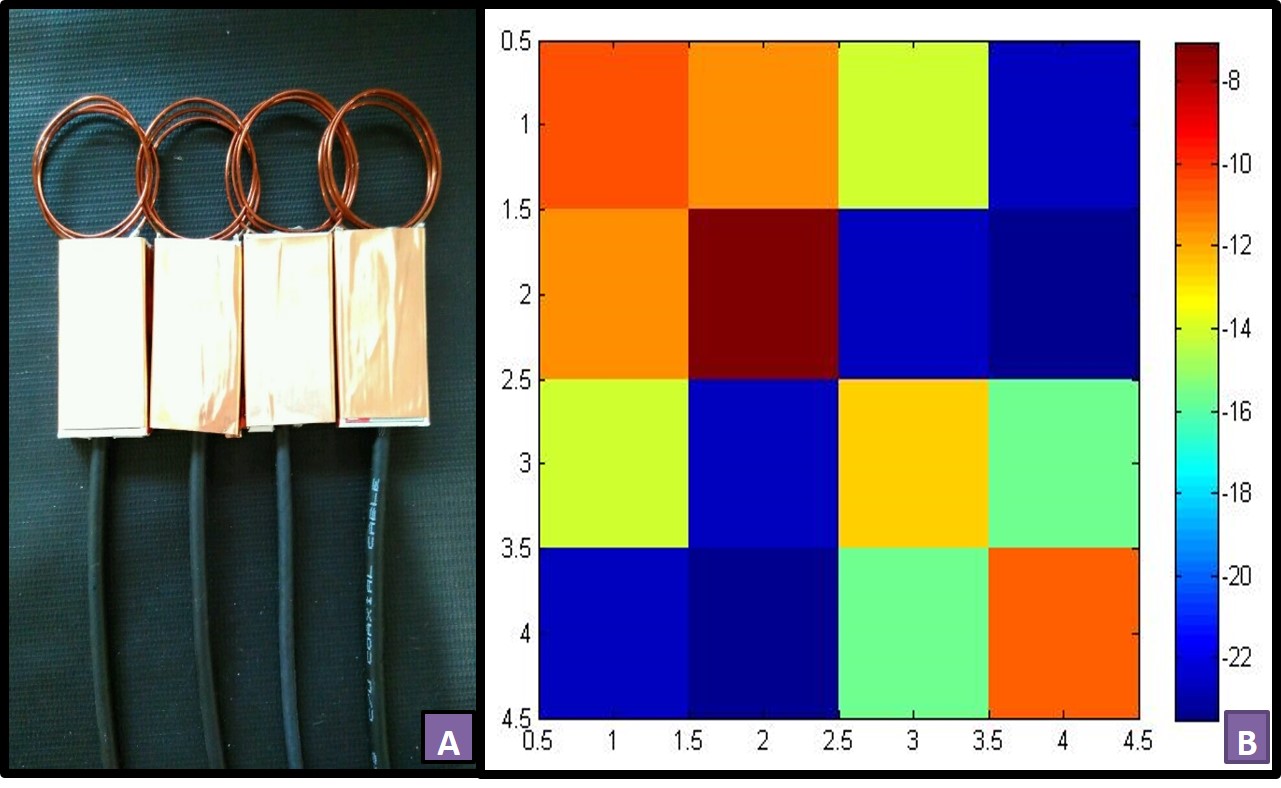
Figure 3A: 4 – Channel phased array. The box shielded with Copper tape contain tuning / matching network.
Figure 3B: S-parameter Matrix in dB
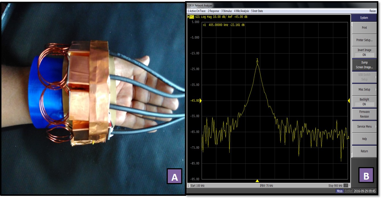
Figure 4A : 4 - channel wrist coil loaded with human hand
Figure 4B : The measured mutual coupling between 4 - channel wrist coils