2714
Design and characterization of an RF shield for a 400 MHz birdcage coil in a retrofitted PET camera for preclinical PET-MRI1Buffalo Neuroimaging Analysis Center, Department of Neurology, Jacobs School of Medicine and Biomedical Sciences, University at Buffalo, The State University of New York, Buffalo, NY, United States, 2MRI Clinical and Translational Research Center, Jacobs School of Medicine and Biomedical Sciences, University at Buffalo, The State University of New York, Buffalo, NY, United States, 3Department of Life, Health and Environmental Sciences, University of L'Aquila, L'Aquila, Italy, 4Laboratori Nazionali del Gran Sasso, Istituto Nazionale di Fisica Nucleare, Assergi, L'Aquila, Italy, 5Dipartimento di Scienze Fisiche e Chimiche, Istituto SPIN-CNR, Coppito, LAquila, Italy
Synopsis
PET-MRI imaging sets the stage for truly novel imaging approaches, but preclinical hybrid systems, characterized by ultra-high static magnetic field and small bore diameter, are still in the proof-of-concept stage. In this study, we developed an optimized RF coil/shield setup for an ultra-high field compatible prototype PET ring that can be retrofitted to conventional small-animal MRI systems. In particular an original shielding solution was designed and tested with the purpose of maximizing coil efficiency, usable space inside the detector, and PET sensitivity.
PURPOSE
PET-MRI benefits from the complementary information provided by the two modalities, setting the stage for truly novel imaging approaches that are currently being explored, such as the use of dual-modality tracers1, the correction of motion effects in (abdominal) PET based on real-time MR information2, and advanced MRI techniques that complement PET3,4,5. While clinical PET-MRI for truly simultaneous imaging are commercially available, such technology for the preclinical setting is still in the proof-of-concept stage6. In this study, we developed an optimized RF coil/shield setup for an ultra-high field compatible prototype PET ring that can be retrofitted to conventional small-animal MRI systems (SynchroPET Inc., Stonybrook, NY).METHODS
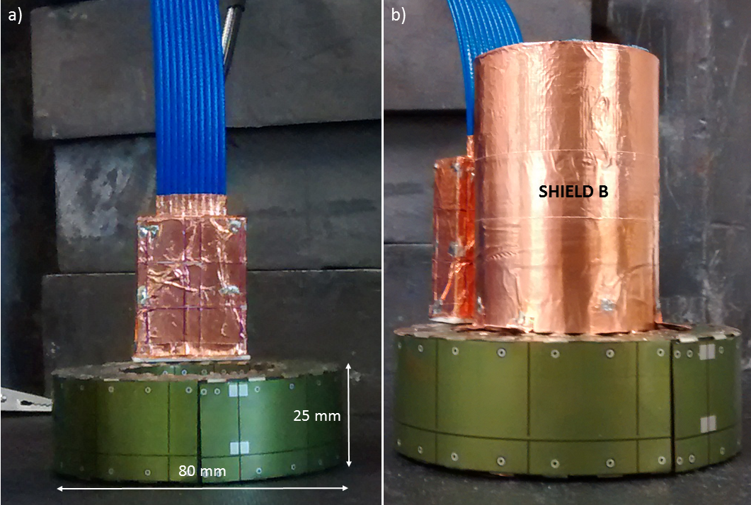
Equipment: The prototype detector ring was based on a previously described platform7, consisting of 12 LYSO crystals (18.5x9.6x6mm3, 4x8 pixels), APD and ASICS microchips, and was enclosed by a dedicated PET RF-shield8 (Fig.1a; internal/external diameter=44/80mm; width=25mm).
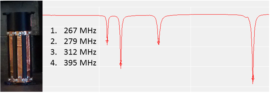
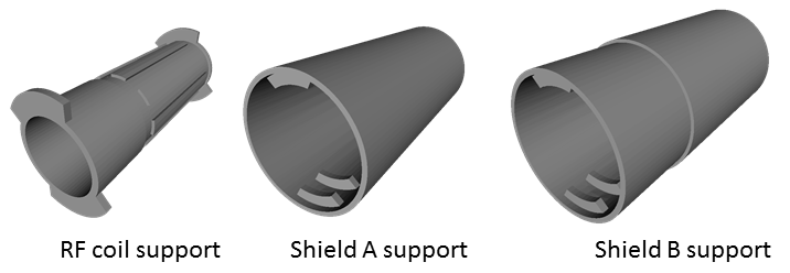
Design of RF coil and shield: Design and experimental considerations focused on maximizing coil efficiency, usable space inside the detector and PET sensitivity. This study was based on a custom high-pass 8 legs birdcage RF coil9 (radius=12 mm, leg-length=570 mm, leg-width=5 mm) with a main resonance frequency of 394.7 MHz and a Q-factor of 90 (Fig. 2). We performed approximate capacitance computation using Java Birdcage Builder (PennState College of Medicine) followed by fine-adjustment with an iterative practical approach. The mechanical support of the RF coil was designed to allow the quick exchange of the RF shield configurations with an inter-locking system, ensuring the coil to be centered inside the RF shield. The parts for the RF shields and coil were designed using Freecad vs 0.16 (Fig. 3) and printed using a fused deposition modeling (FDM) 3D printer (Rostock Max v.2; ABS). Conductive elements of the RF shields and coil were made by using copper tape (thickness 50 µm). For the final RF coil, we employed 10 pF tuning capacitors (250 VDC, size 1206). We developed two different RF shields: (i) one extending over the whole RF coil length and fully inserted into the PET ring (shield A, diameter=41.5mm); and (ii) one with external diameter like the inner diameter of PET ring’s own RF shield such that both RF shields covered the whole RF coil length (shield B, Fig.1b, diameter=44mm) (Fig. 3). To allow electrical continuity, the shield B was connected to the PET ring’s RF shield with copper stripes.
Experiments: Coil characterization and measurements were performed using a 1.3 GHz Vector Network Analyzer (DG8SAQ VNWA, SDR-Kits, Germany). To determine the main resonance frequency, we measured the maximum peak shift for the 4 characteristic frequency modes of the RF coil without shield upon perturbation of the center of the coil with a metallic insert at the end of a plastic stick. Subsequently, we measured the Q-factor and mean frequency inside the powered/unpowered PET ring: (i) without the RF shield; (ii) with shield A; and (iii) with shield B. Moreover, the measurements were made outside the ring with no RF shield and with the shield A. We determined the absorption of gamma-photons by the copper RF shield using a Na-22 point source (50 μCi; MMS09-22, Eckert&Ziegler) inside the RF coil by measuring the single counts rate over five minutes for each of the 3 RF shield configurations.
RESULTS
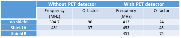
The Q-factor and frequency measurements are reported in Table I. As expected, the presence of the PET ring strongly affected the unshielded RF coil, substantially shifting the resonance frequency and decreasing the Q-factor. No significant changes of Q-factor and frequency were noticed in the presence of the shield A. Shield B yielded the highest Q-factor. No changes were detected with the PET camera turned on/off. A minor decrease in single counts rate was detected in configuration A (50.19 kcps) compared to the conditions with no shield (50.46 kcps) and shield B (50.63 kcps).DISCUSSION
Our experiments illustrated the need for a dedicated RF coil shield design to avoid coupling between the RF coil and PET ring’s shield, while maintaining the RF coil’s sensitivity. The comparison between single count rates in the 3 different configurations showed that the additional copper layer of shield A does not substantially decrease the PET sensitivity. However, shield B showed a substantially greater Q-factor, which may be explained by the larger ratio between the shield diameter and the coil diameter. The higher Q-factor may be traded for a larger RF coil to increase the usable space for imaging.CONCLUSION
Our study showed that an extension RF shield represents the optimal RF coil shielding configuration for an ultra-high field retrofitted PET camera.Acknowledgements
This work was supported in part by the University at Buffalo Center for Advanced Biomedical and Bioengineering Technology (UB CAT) and by theNational Center for Advancing Translational Sciences of the National Institutes of Health under award Number UL1TR001412. The content is solely theresponsibility of the authors and does not necessarily represent the official views of the NIH.References
1. H.-y. Lee, Z. Li, K. Chen, A. R. Hsu, C. Xu, J. Xie, S. Sun, and X. Chen, “PET / MRI Dual-Modality Tumor Imaging Using Radiolabeled Iron Oxide Nanoparticles,” J. Nucl. Med., vol. 49, no. 8, pp. 1371–1379, 2008.
2. S. Y. Chun, T. G. Reese, J. Ouyang, B. Guerin, C. Catana, X. Zhu, N. M. Alpert, and G. El Fakhri, “MRI-Based Nonrigid Motion Correction in Simultaneous PET/MRI,” Journal of Nuclear Medicine, vol. 53, no. 8, pp. 1284–1291, 2012.
3. T. Stadhouders, A. Savio, J. Diehl-Schmid, C. Sorg, T. Grimmer, and I. Yakushev, “Alterations in neurocognitive networks in dementing disorders as assessed with simultaneous PET/fMRI,” J. Nucl. Med., vol. 57, no. supplement_2, pp. 237–, may 2016.
4. S. Bisdas, R. Ritz, B. Bender, C. Braun, C. Pfannenberg, M. Reimold, T. Naegele, and U. Ernemann, “Metabolic Mapping of Gliomas Using Hybrid MR-PET Imaging: Feasibility of the Method and Spatial Distribution of Metabolic Changes.” Investigative Radiology, vol. 00, no. 00, pp. 1–7, 2013.
5. K. Simonyan, P. Herscovitch, and B. Horwitz, “Speech-induced striatal dopamine release is left lateralized and coupled to functional striatal circuits in healthy humans: A combined PET, fMRI and DTI study,” NeuroImage, vol. 70, pp. 21–32, 2013.
6. Vandenberghe, Stefaan, and Paul K. Marsden. "PET-MRI: a review of challenges and solutions in the development of integrated multimodality imaging." Physics in Medicine and Biology 60.4 (2015): R115.
7. S. H. Maramraju, S. D. Smith, S. S. Junnarkar, D. Schulz, S. Stoll, B. Ravindranath, M. L. Purschke, S. Rescia, S. Southekal, J.-F. Pratte, P. Vaska, C. L. Woody, and D. J. Schlyer, “Small animal simultaneous PET/MRI: initial experiences in a 9.4 T microMRI.” Physics in Medicine and Biology, vol. 56, no. 8, pp. 2459–80, 2011.
8. S. H. Maramraju, S. D. Smith, S. Rescia, S. Stoll, M. Budassi, P. Vaska, C. Woody, and D. Schlyer, “Electromagnetic interactions in a shielded PET/MRI system for simultaneous PET/MR imaging in 9.4 T: Evaluation and results,” IEEE Transactions on Nuclear Science, vol. 59, no. 5 PART 1, pp. 1892–1899, 2012.
9. Leifer, Mark C. "Resonant modes of the birdcage coil." Journal of Magnetic Resonance 124.1 (1997): 51-60.
Figures