2711
Improved Decoupling for 13C Coil Arrays Using Non-Conventional Matching and Preamplifier Impedance1Department of Electrical Engineering, Technical University of Denmark, Kgs. Lyngby, Denmark, 2Department of Clinical Medicine, Aarhus University, Aarhus, Denmark
Synopsis
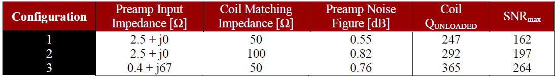
In this study, we describe a method to obtain improved preamplifier decoupling for receive-only coils. The method relies on the better decoupling obtained when coils are matched to an impedance higher than 50 Ω. Preamplifiers with inductive imaginary impedance and low real impedance, increases the effectiveness of the decoupling. A 2-channel 13C array of 50 mm loop coils show an increase of Q-factor of the coils from 247 to 365. The measured SNR, using two small phantoms, demonstrated a similar improvement.
Purpose
Arrays of small coils are challenging due to the low sample loading (high Q) and strong coupling between elements, and the difficulty of decoupling them without compromising the Q-factors of the individual coils. Preamplifier decoupling as described in1 (and further developed in2) can potentially overcome the problem, but for high-Q coils, a very low input impedance is needed in order to obtain a reasonable decoupling. However, for the case of 13C at 3 T (32.13 MHz), commercially available preamplifiers3 have input impedance over 2.5 Ω, which for high-Q coils (>300) provide very modest decoupling (<13 dB) in the standard configuration. Here we show that matching the coils to a higher impedance than the noise-optimum of the preamplifier (usually 50 Ω) can be beneficial to improve the decoupling. The effect can be improved even more, if the preamplifier shows an inductive impedance at its input (with low real part).Methods
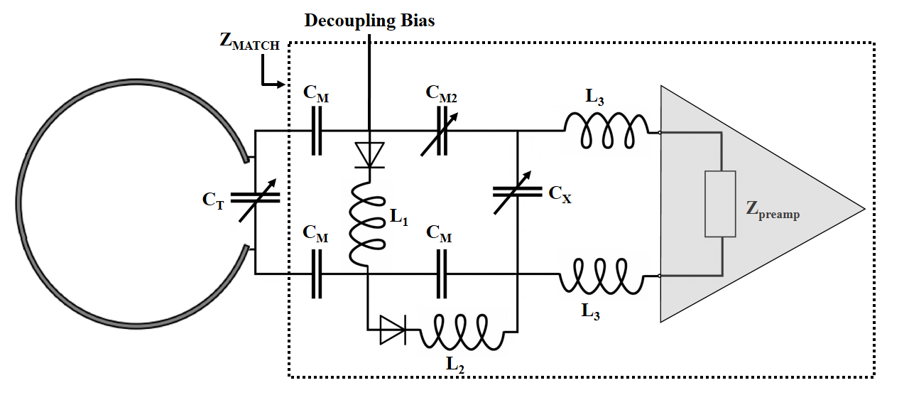
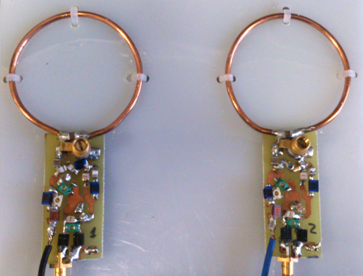
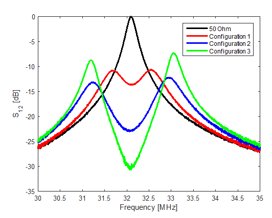
A modification of the circuit proposed in2 is used, in combination with the active decoupling scheme proposed in4 (Fig. 1). This circuit allows keeping the active decoupling from the transmitter independent of the inductance used for the preamplifier decoupling (L3), which is practical when the preamplifier decoupling needs to be finely tuned (as is the case in high Q coils). A 2-channel array was built (Fig.2), using wire loop coils (coil diameter 50 mm, wire diameter 2.3 mm) separated by 75 mm (corresponding to next near neighbors in an overlapped array). The preamplifier decoupling performance was measured as the difference of S12 [dB] of a loosely coupled double-loop probe between the 50 Ω and the preamplifier load. The Q-factor of the coils when mounted in the array was measured from the S11. Experiments were repeated using a commercial preamplifier with resistive low input impedance (WMA32C, WanTCom, Chanhassen, MN, USA) matched to 50 and 100 Ω, and a self-made preamplifier (more details in a separate abstract) with an inductive input impedance and matched to 50 Ω. The parameters of the preamplifiers are shown in Table 1. Imaging experiments were performed at a clinical 3 T scanner (Signa HDx, GE Healthcare, Waukesha, WI, USA) using two spherical (38 mm diameter) 13C-enriched bicarbonate phantoms, placed on top of each coil and separated 1 mm from them. The sequence used was a regular CSI with a 16x16 matrix, TR = 75 ms, 19 s total duration, and FOV of 120x120x50 mm3.Results
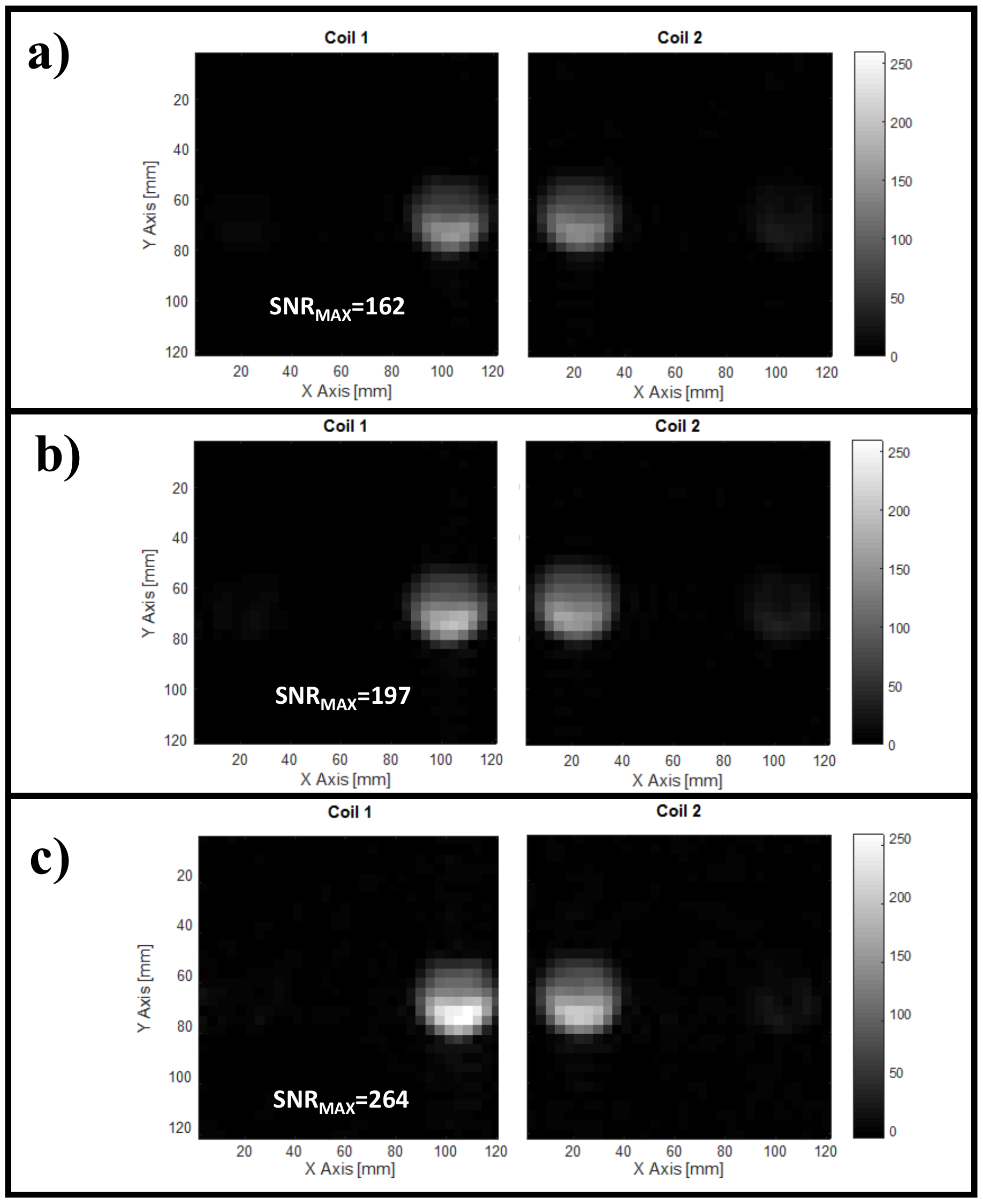
The measured coil Q-factor and maximum SNR are summarized in Table 1. The decoupling is shown in Fig. 3 and the obtained images in Fig. 4, for the 3 different preamplifier configurations tested. The coil Q-factor for the different configurations is consistent with the measured decoupling. The better Q of the coils translates to better measured SNR, which shows that the coils are working on the coil-noise dominated domain.Discussion
Non-conventional coil matching can provide better preamplifier decoupling when using the circuit proposed in2, and can be used to obtain better SNR as long as the noise figure of the preamplifiers is still good at the impedance chosen for matching. In this study, we show that matching to a higher impedance using traditional low input impedance preamplifiers improves the preamplifier decoupling and can be beneficial in terms of SNR for coils where thermal noise is dominant, due to the improved Q-factor of the coils. This effect can be exploited even further if the preamplifier presents an inductive input impedance, therefore allowing the matching with a higher capacitance value (CM in Fig.1). This is so, because at the frequency of interest, the impedance of the matching network (ZMATCH) becomes a bandpass filter when the preamplifier is connected. This creates a current divider with the resonator formed by the loop and CT. Therefore, the amount of current reduction in the loop is inversely proportional to ZMATCH (being ZMATCH lower when the coil is matched to a higher impedance2).Conclusion
A practical setup providing improved decoupling for 13C coils at 3 T has been demonstrated on a 2-channel array of small coils. An improvement of 30 % on the maximum measured SNR was found when matching the coils to a slightly higher impedance (100 Ω) with commercial preamplifiers. An even higher, 60 %, improvement was obtained with the use of preamplifiers with inductive input impedance. This decoupling method is of particular interest for arrays of small coils and/or low frequency, where coil noise dominates, and the coupling between elements is a major source of electronic noise.Acknowledgements
This work has been partly funded by the Danish Council for Independent Research (DFF – 4005-00531) and the Danish National Research Foundation (DNRF124).References
1. Roemer, Peter B., et al. "The NMR phased array." Magnetic resonance in medicine 16.2 (1990): 192-225.
2. Reykowski, Arne., et al. "Design of matching networks for low noise preamplifiers." Magnetic resonance in medicine 33.6 (1995): 848-852.
3. WanTcom Inc. WMA32C Datasheet. (2013).
4. Sanchez-Heredia, Juan D., et al. "Decoupling Scheme for a Cryogenic Rx-Only RF Coil for 13C Imaging at 3T." ISMRM 2016 Annual Meeting & Exhibition. 2016.
Figures