2709
A technique to compensate signal loss in an RF switch matrix system in MRI1Institute of Neuroscience and Medicine - 4, Forschungszentrum Juelich, Juelich, Germany, 2School of Electrical and Electronics Engineering, Chung-Ang University, Seoul, Korea, Republic of, 3Faculty of Medicine, Department of Neurology, JARA, RWTH Aachen University, Aachen, Germany
Synopsis
MRI RF channels refer to the pathways of received signals and the availability of multiple channels allows one to access multi-channel array coils. To control the use of different coils, MRI usually utilises a crossbar-type switch matrix system that interactively connects the selected coil as an input and corresponding analogue-to-digital converters as an output. However, since the RF wavelength decreases with increasing B0, impedance in RF pathways varies in accordance with wavelength. This results in signal loss and in degraded image quality. In this study, we proposed an RF loss compensation technique for the switch matrix and verified its performance.
Purpose
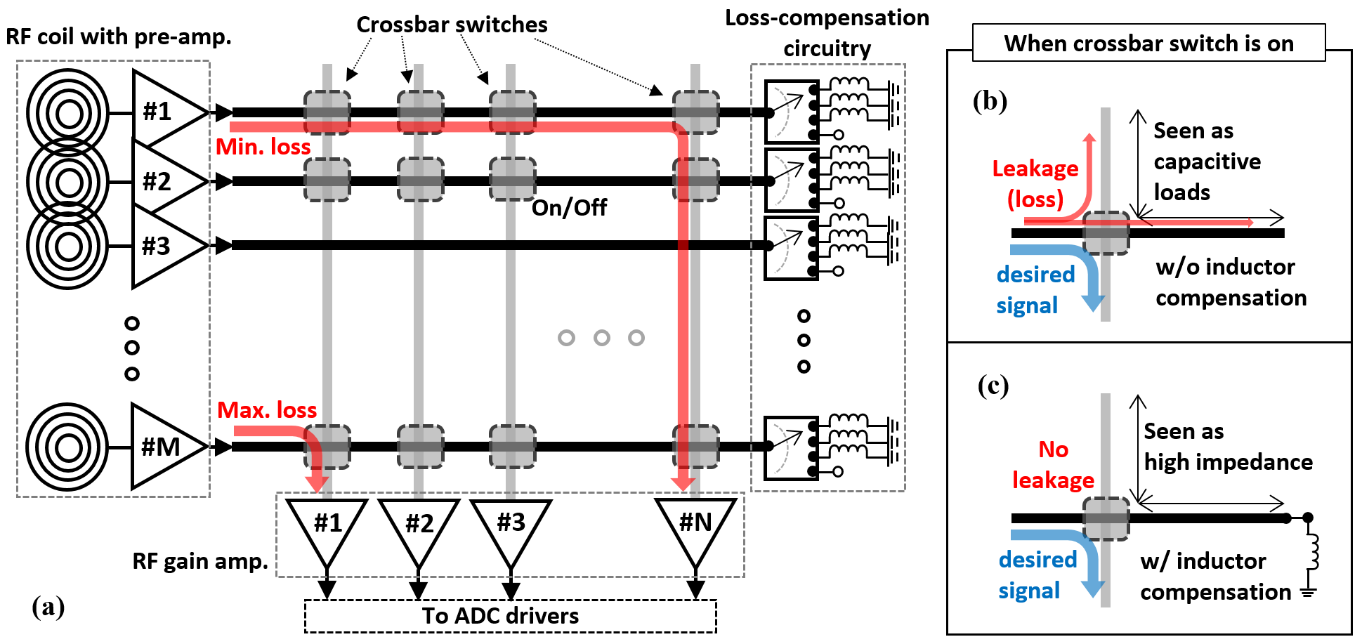
MRI RF channels refer to the pathways of received MR signals and the availability of multiple RF channels allows one to access multi-channel phased array coils and to achieve faster acquisition1. In order to control the use of different types of RF coils, MRI system usually utilises a crossbar-type switch matrix system (Fig. 1) that interactively connects the selected RF coil as an input and corresponding analogue-to-digital converters (ADC) as an output2. However, since the RF wavelength decreases with increasing magnetic field strength, impedance in RF pathways varies in accordance with wavelength3. This results in signal loss and in degraded image quality. In this study, we proposed an RF loss compensation technique for the switch matrix and we have verified its performance.Methods
The crossbar-type switch matrix illustrated in Fig. 1 is configured independently by vertical and horizontal RF transmission lines in an M x N matrix with an M x N number of crossbar switches. The crossbar switch connects the vertical and horizontal paths according to turning on and off operations. However, when a crossbar switch is turned on, the disconnected section of transmission line along with the desired signal path acts as a microwave open-stub (capacitive load) instead of purely high impedance (open-circuit). It is often noticed that the length of the open-stub is changed which can be equivalent to the quarter-wavelength (λ/4) of the system Larmor frequency where high impedance is transformed into low impedance. This results in RF signal leakage and in degradation the signal-to-noise ratio (SNR). Therefore, in order to cancel out the capacitive load effects at the MR operation frequency, a loss-compensation unit consisting of inductor banks has been inserted as shown in Fig. 1. Here, RF gain amplifiers are connected at the outputs of the switch matrix in order to provide sufficient signal level before the ADCs. When the desired RF signal path has a relatively short length of open-stub, for example, RF coil #1 to RF gain amplifier #N, the loss-compensation circuitry is turned on. However, when the desired RF signal path has a relatively long open-stub (for example, RF coil #M to RF gain amplifier #1), the loss-compensation circuitry is switched to the corresponding inductor to ensure high impedance. The switch-controlled inductors and capacitances introduced by open-stubs resonate at the operation frequency and turn it into high impedance, resulting in minimising the signal loss. Thus, to observe the effect of open-stubs and inductor compensation on the MR image, a switch matrix containing the loss-compensation circuitry based on inductors was constructed using a 15 mm thick FR4 in 300 mm x 210 mm size.Results
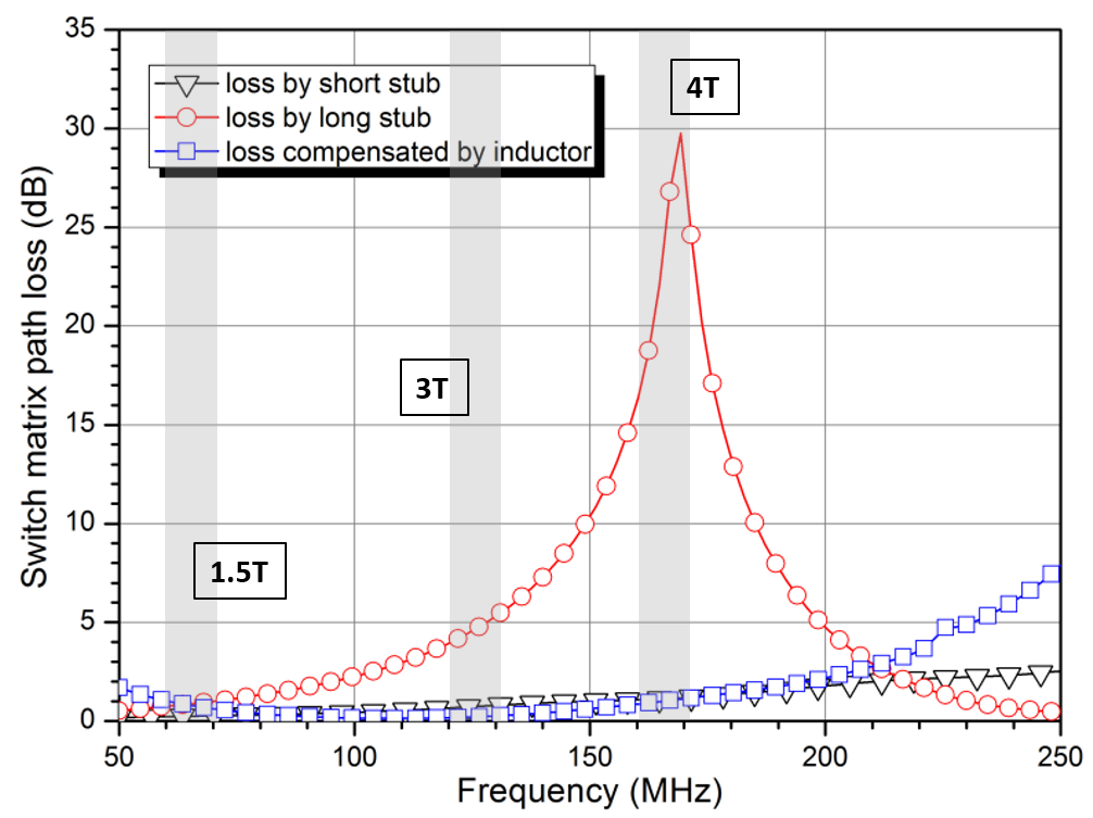
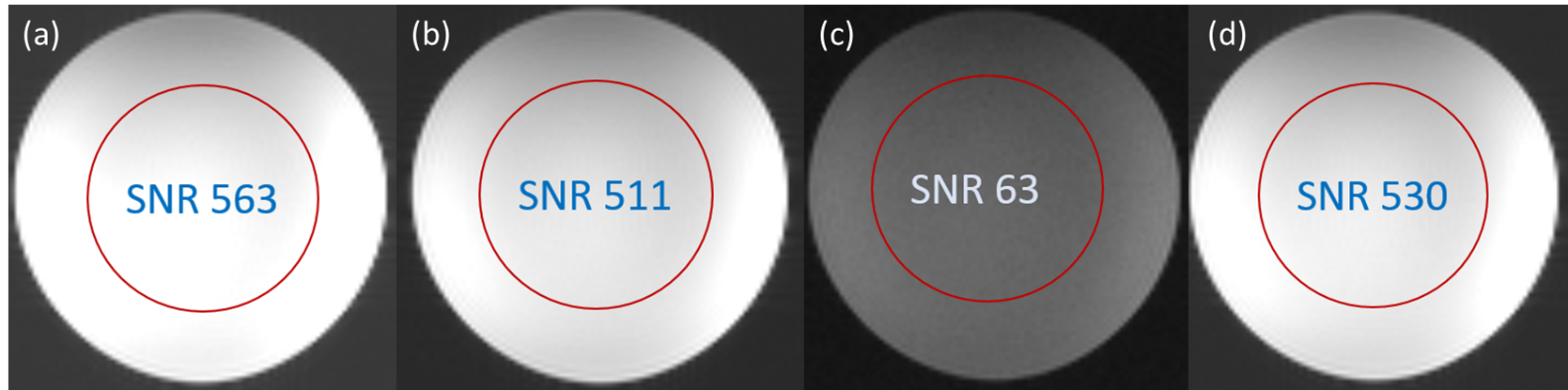
S-parameters was measured and the proposed switch matrix was initially evaluated on the bench. Figure 2 shows the path losses measured on the condition of short open-stub (~5 cm), long open-stub (~24 cm) and inductor compensation (22 nH). At 170 MHz (1H Larmor frequency at 4T), the path with short open-stub, long open-stub and inductor compensation showed about 1.2, 29.5 and 1.1 dB losses, respectively. The proposed switch matrix was tested using a single loop RF coil on a 4T MR system. Having the SNR obtained without any open-stub effects as a reference, the SNR for the case having the 5 cm open-stub showed 9% degradation. In the worst case where the length of the open-stub was about 24 cm, the SNR was decreased by approximately 88%. In the similar manner but with the inductor compensation, the SNR was dropped by 6 % only; a more than 80% improvement. Figure 3 shows the MR axial images obtained using (a) without the switch matrix board (reference), (b) short open-stub, (c) long open-stub and (d) inductor compensation.Discussion
We have demonstrated that the loss compensation technique performed well enough to be of use in the switch matrix. It is expected that a multi-channel RF switch matrix may be significantly affected by the lengths of open-stub resulting in severe SNR degradation. By use of this proposed loss-compensation technique, the SNR degradation can be overcome and high image quality at ultra-high MR system can be achieved.Acknowledgements
No acknowledgement found.References
[1] Parikh PT, Sandhu GS, Blackham KA, Coffey MD, Hsu D, Liu K, Jesberger J, Griswold M and Sunshine JL. Evaluation of Image Quality of a 32-Channel versus a 12-Channel Head Coil at 1.5T for MR Imaging of the Brain. AJNR Am. J. Neuroradio.2011;32;365-373.
[2] Horst Kröckel. (2010). " Switching matrix with two control inputs at each switching element", US Patent 7,684,427, to Siemens Aktiengesellschaft, 2010.
[3] Pozar D.M. Microwave Engineering. John Wiley & Sons Inc. 1998
Figures