2708
In-Bore High Efficiency Current Driver1Dept of Radiology, Case Western Reserve University, Cleveland, OH, United States
Synopsis
Recent work has shown the use of shim and gradient coil arrays for dynamic shimming and novel spatial encoding methods. These arrays require precise current source drivers with high power and bandwidth. Because of these demands, shim and gradient arrays are typically driven with amplifiers which are located outside the magnet bore due to constraints on power dissipation, radiofrequency interference (RFI), or magnetic materials. Here we present a highly efficient digitally-controlled switchmode current driver. We demonstrate that it is feasible to shield the RFI from the receive chain while avoiding ferrous materials and large heatsinks.
Purpose
Recent work has demonstrated the use of local coil arrays for dynamic B0 shimming1-3. Coil arrays may also be used in matrix gradients to achieve unique spatial encoding schemes. In such work, switchmode gradient power amplifiers and switch matrices are used4. In each case, the amplifiers are located remotely, either due to their high power dissipation or magnetic components. Ideally, switchmode amplifiers could be placed near the array in order to minimize power dissipation while maintaining high output bandwidth and reducing cabling constraints. However, radiofrequency interference (RFI) from switchmode power supplies (SMPS) may easily contaminate the RF receive chain, causing severe imaging artifacts. Here we present a switchmode current source designed to operate within the constraints of the MRI bore.Methods
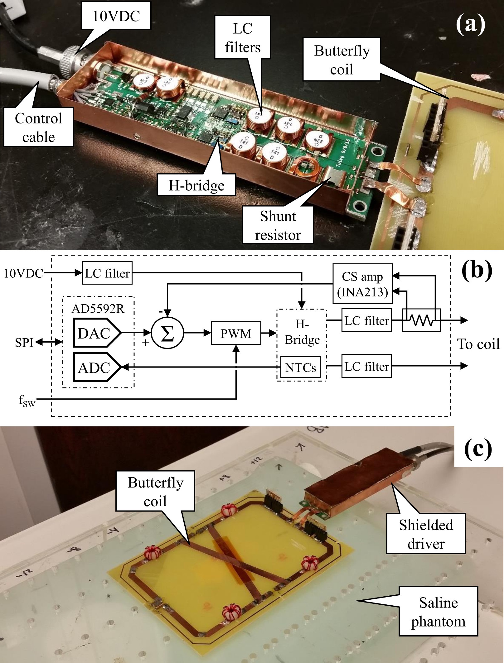
Amplifier stage: The amplifier is an H-bridge whose operating frequency is set by an external reference clock. EPC2015C eGaN FETs are used to achieve high efficiency at high fSW≈2MHz. Each bridge output is fed through a two stage LC filter. The H-bridge stage is biased with 10VDC which is also filtered by a two stage LC filter. All components were nonmagnetic, with the exception of nickel plating in component terminals.
Output current control: The output current IL is monitored with a shunt resistor and low-drift differential amplifier. A type III error amplifier and PWM modulator close a negative feedback loop with 40kHz of bandwidth. The setpoint for the output current comes from an AD5592R DAC/ADC. The AD5592R also monitors the temperature of each bridge using thermistors. A shielded cable carries the AD5592R’s SPI port signals and the reference clock. A copper faraday cage is soldered to the PCB in order to suppress RFI. Figure 1 shows a photograph and block diagram of the driver.
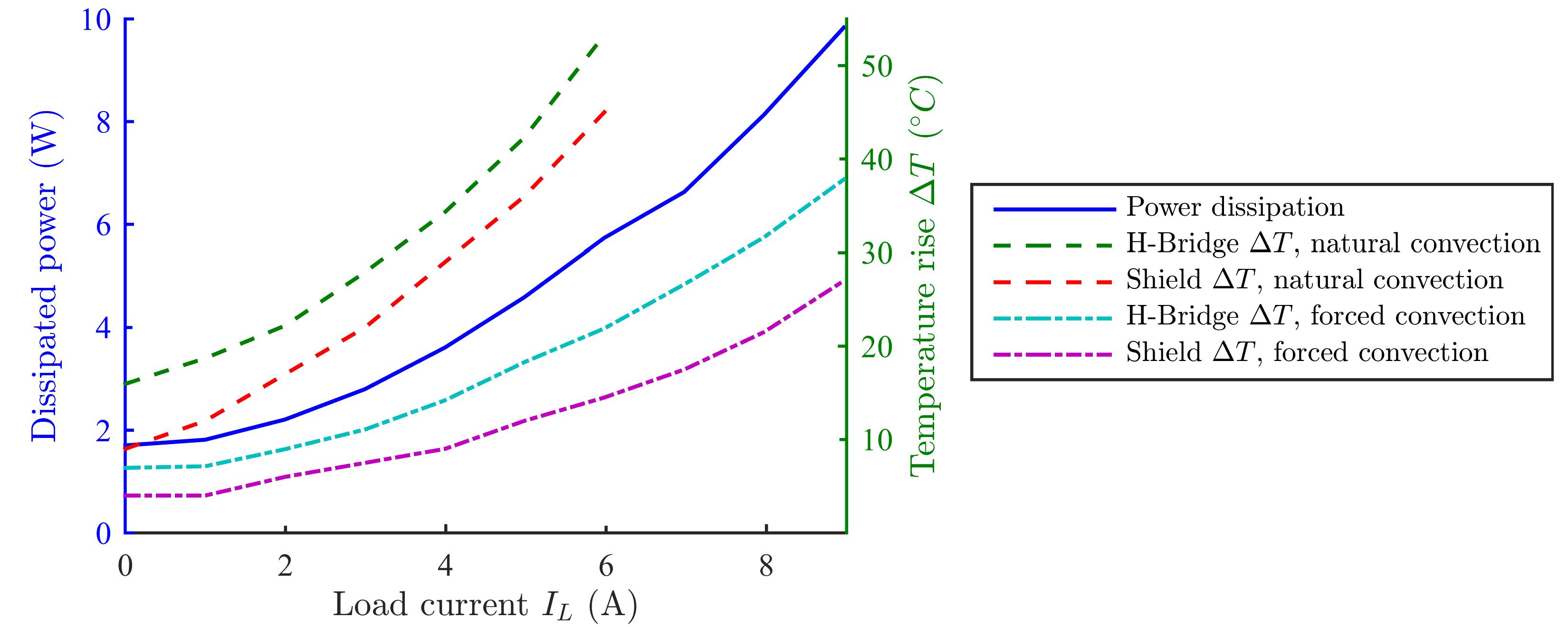
Benchtop testing: The module was loaded with a butterfly coil (L=1.5µH, ESR=95mΩ,) while IL was varied across its full range of +/-9A. For each IL, the steady state temperatures of each thermistor and the shield exterior were measured. This was performed with both natural and forced convection.
Imaging experiments: To ensure that RFI from the driver does not impact image quality, experiments were performed while operating the module and coil inside the bore of a Siemens Skyra 3T scanner. A saline phantom was placed on the spine array, and the module/coil was placed 2cm above the phantom. Δf maps were then derived using a variable TE FLASH sequence with high readout bandwidth (385kHz). Maps were acquired to measure the amplifier’s impact on B0 inhomogeneity, and map the B0 produced by its shim current.
Results
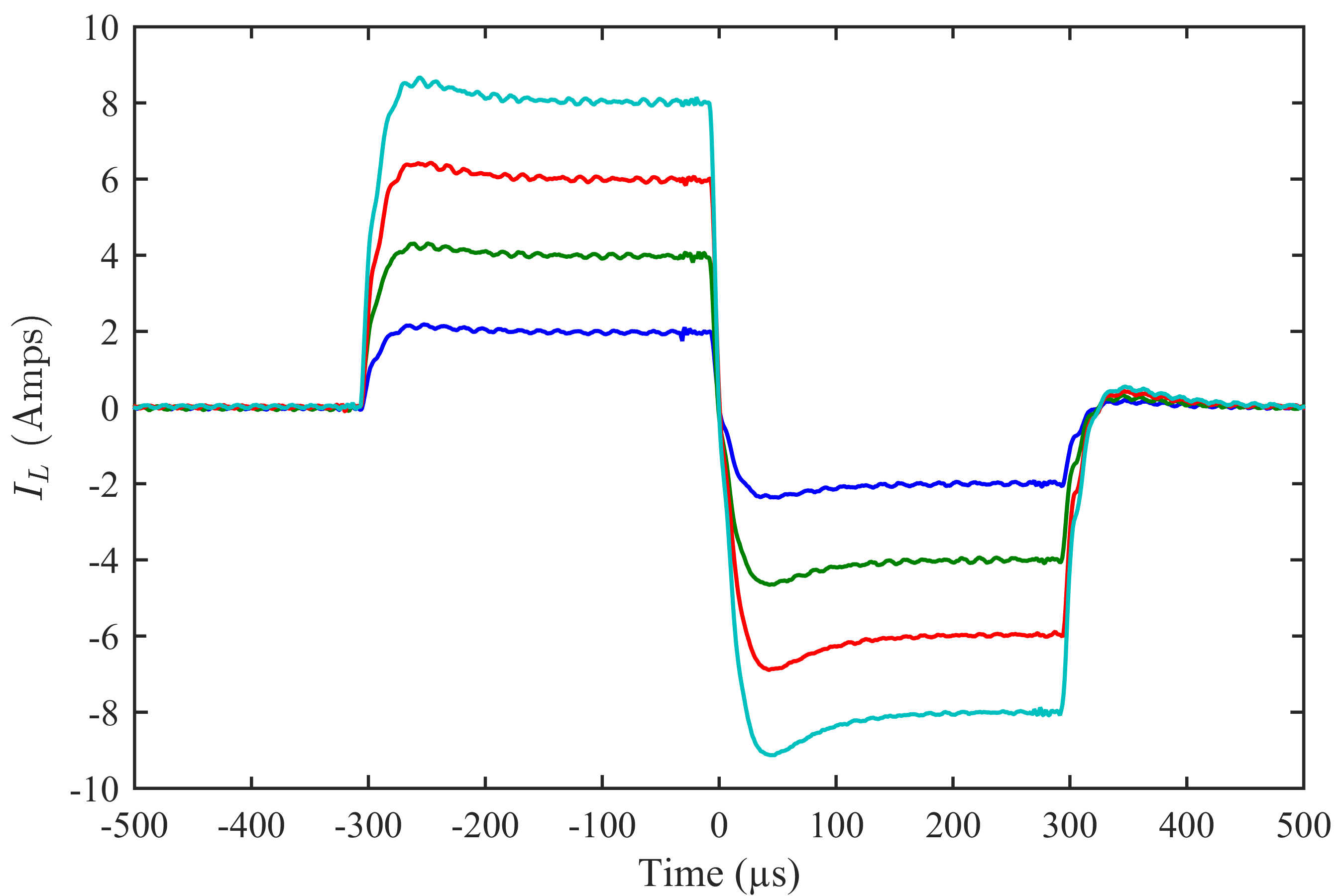
Power dissipation: Figure 2 shows power dissipation and temperature rise vs IL. With forced convection, IL was swept through the full range of +/-9A with only 10W maximum dissipation. With natural convection, IL was limited to +/-6A in order to limit the bridge temperature to 70 °C. Figure 3 shows the response of IL to bipolar current pulse commands. The maximum drift observed in IL was 1.8mA.
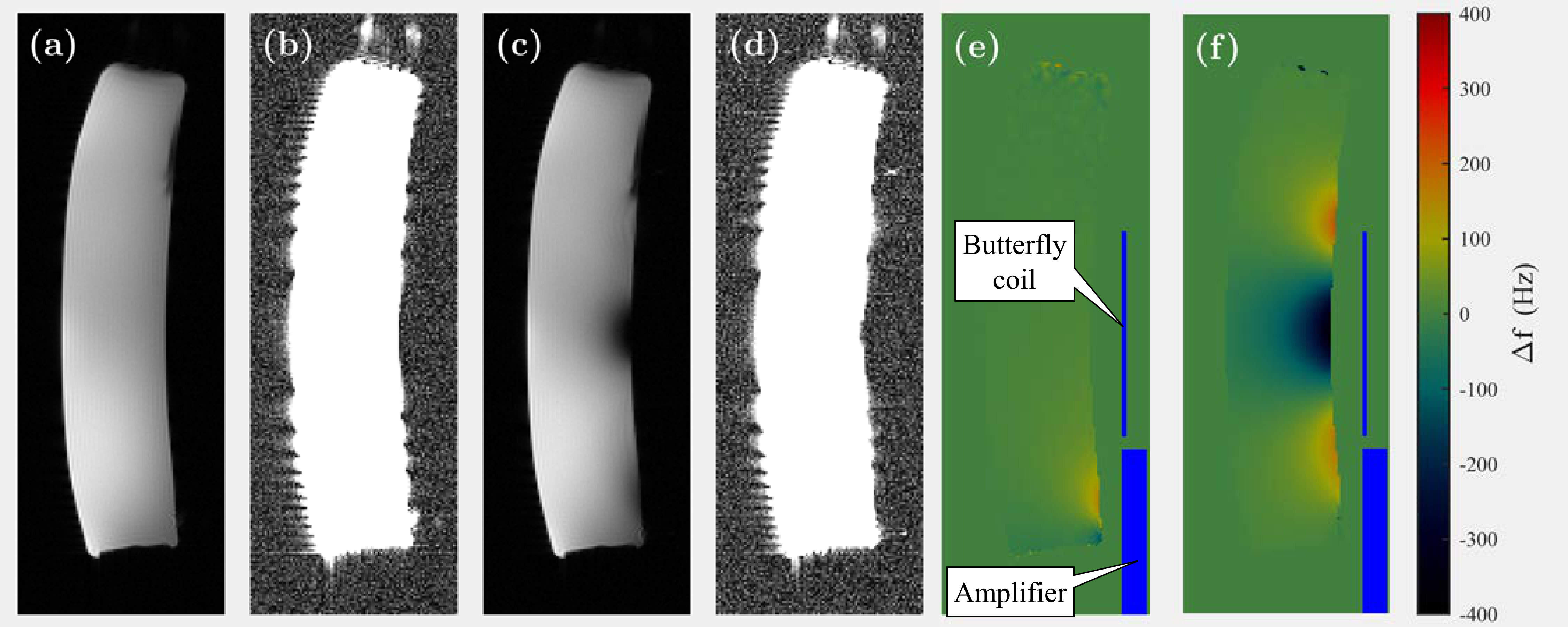
Imaging experiments: Figure 4 (a) shows a reference image of the phantom alone, while (c) shows the effects of the presence of the amplifier and coil with IL=6A. (b) and (d) show the same images with increased intensity. Figure 4 (e) shows the Δf maps due to the module with no power applied. Figure 4 (f) shows the calculated sensitivity map of the shim coil, in Hz per unit amp. The background noise in the images was observed to rise by 4% when the amplifier and cables were introduced, but unpowered. The background noise when the amplifier operates at IL=6A was observed to rise by an additional 1%. This suggests that the majority of interference is due to cable pickup, and not generated from the circuit itself.
Discussion and Conclusion
We have demonstrated that by operating a SMPS with a frequency much higher than the receiver bandwidth, we are able to avoid RFI contamination of the MRI receive chain. The driver provides up to +/-10V and +/-9A with a 20 µs rise/fall time, yet only dissipated 10W at its maximum current, as opposed to an equivalent linear amplifier which would need to dissipate at least 80W. The maximum RMS load current is heavily dependent on thermal considerations. These results suggest that if the shield is properly cooled, continuous output currents up to 20A and pulsed currents up to 40A may be feasible. Such a SMPS has potential applications not only in dynamic shimming and spatial encoding, but in any electrical system requiring regulated DC current or voltage near the bore.Acknowledgements
This work was supported by Siemens healthcare.References
1. Juchem, C., Umesh Rudrapatna, S., Nixon, T. W. & de Graaf, R. A. Dynamic multi-coil technique (DYNAMITE) shimming for echo-planar imaging of the human brain at 7 Tesla. NeuroImage 105, 462–472 (2015).
2. Stockmann, J. P. et al. A 32-channel combined RF and B 0 shim array for 3T brain imaging: Combined RF and B0 Shim Array. Magnetic Resonance in Medicine 75, 441–451 (2016).
3. Han, H., Song, A. W. & Truong, T.-K. Integrated parallel reception, excitation, and shimming (iPRES). Magnetic Resonance in Medicine 70, 241–247 (2013).
4. Yu, H. et al. An improved design of multi-channel switching circuit for matrix gradient coil. 23rd ISMRM (2015).
Figures