2707
A 16 Element Bow-Tie Slot Array Coil for Parallel Transmit MRI/MRS1Electrical and Computer Engineering, Texas A&M University, college station, TX, United States, 2Electrical and Computer Engineering, Texas A&M University
Synopsis
We report a volume coil consisting of 16 bowtie slot elements arranged in eight independent modules. The slot coils provide several interesting advantages over conventional elements. In particular they demonstrate a high degree of Intrinsic coupling between modules, making this array ideally suited for use in parallel transmit using conventional amplifiers. Additionally, all match and tune elements, baluns and feedlines are concealed between two ground planes, shielding the imaging volume from stray electric fields. Imaging results are shown at 4.7 Tesla demonstrating isolated patterns and a broad coverage in volume coil mode.
Target Audience:
Researchers and practitioners interested in array coils and array elements for transmit or transmit/receive multi-channel MRI.Purpose:
The rapidly increasing availability and interest in multichannel transmit coils has generated a number of interesting new element designs. The slot element has demonstrated good potential for use in high field MRI, however, it has a narrow coverage in the sagittal and coronal planes1,2. Here we report a volume coil consisting of 16 bowtie slot elements arranged in eight independent modules, each of which contains two bowtie slots excited by forced-current excitation. The array exhibits high intrinsic decoupling between modules, making this array ideally suited for use in parallel transmit using conventional amplifiers. Additionally, the module matching network and feed lines are placed behind the RF shield that is inherent in slot antenna designs, shielding the imaging volume from stray electric fields.Methods:
Parallel transmit MRI requires mitigating the effects of coupling between the elements, which can be achieved through intrinsically isolated array elements, isolating amplifier design, decoupling networks, or software decoupling of the channels. Intrinsically isolated elements have the advantage of much simpler implementation as compared to the other options. The slot element has the unique advantage that it operates as part of a ground plane, or shield, rather than above the shield. This simplifies any concerns with interactions between the transmit array and any receive array, if one is to be used.
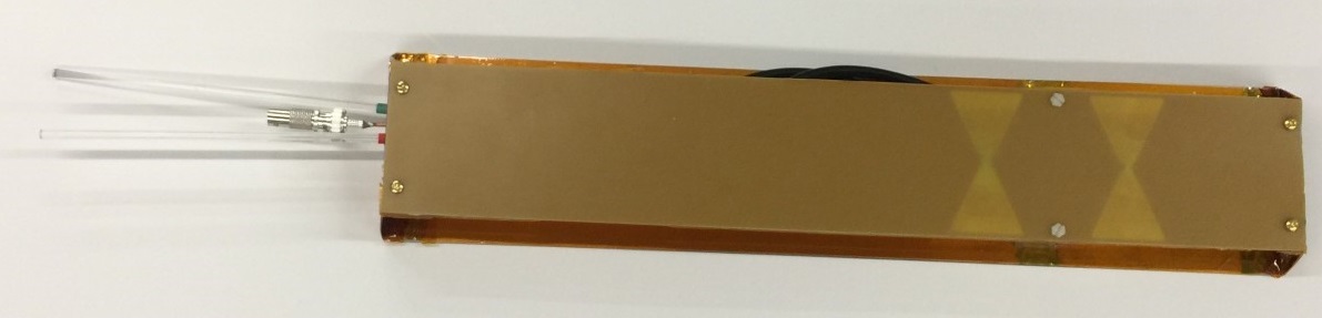
Here we introduce a dual element bow-tie slot module that is shown in Figure 1. Each slot has a length of 7 cm and a width of 3.5 cm at the widest point, with a 7 cm center-to-center spacing between them. The bowtie configuration was found to provide higher sensitivity and radiation resistance than a simple thin slot through electromagnetic modeling (Xfdtd 7.5, Remcom, State College, PA, USA). In order to provide significant coverage in the sagittal and coronal planes, each module consists of two slots which are individually excited using forced current excitation. This delivers equal current to the two slot elements and can also be upgraded in the future to allow selectively exciting or detuning one element according to the desired FOV 3.
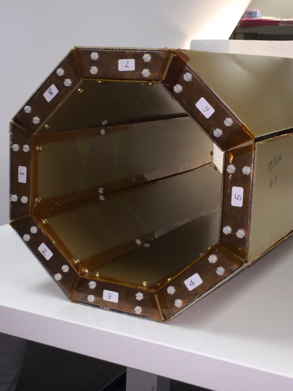
Eight dual-slot modules were configured to form a volume coil as shown in Figure 2. Importantly, the internal imaging volume is surrounded by an RF shield into which the slots are cut. Each slot is excited from behind the shield by a twin-axial cable connected across the narrow point of the bow-tie element. The balun, matching network, and feed lines are also located behind the RF shield, with an additional ground plane 2.54 cm behind the slot plane.
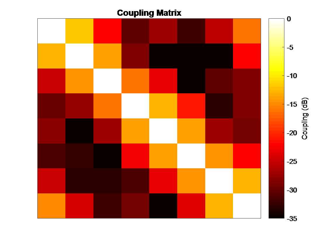
The volume array had an inner diameter of 20 cm and an outer diameter of 25.5 cm, to fit inside the 26 cm diameter of the gradient set in our scanner. The coupling matrix was obtained with all elements matched to -20dB return loss or better. Each element was connected to one channel of a prototype 64 channel transmitter. Single channel transmit/receive images were obtained from each element on a 4.7T/40 cm Varian Inova scanner, operating at 200 MHz. Finally, based on initial phase maps, a ‘birdcage’ mode was set to check for the ability to generate a field in the center.
Results:
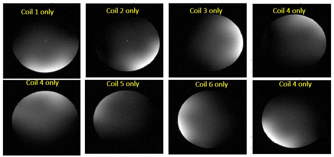
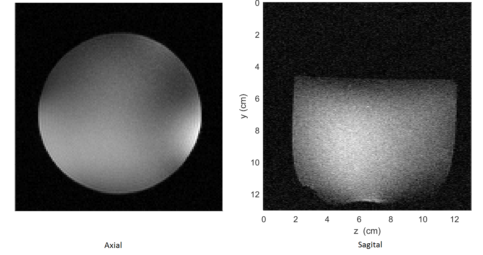
The coupling matrix is shown in Figure 3. The worst case did not exceed -12dB. This was achieved without the need to employ any decoupling networks or other techniques, indicating a high degree of intrinsic isolation between the modules. The individual module patterns taken in a transverse plane at the midpoint between the two slots show excellent isolation, as seen in figure 4. A simple 'birdcage' excitation was generated using eight transmit channels with equal magnitude and manually adjusted phases. The right and left module were used for receive and a sum-of-squares reconstruction was performed. The result is improved uniformity, though a more robust phase-magnitude adjustment method would yield further improvements.Discussion:
This slot array appears ideally suited for use in a multi-channel transmit array due to the high degree of intrinsic isolation between elements and the ‘clean’ environment it provides for adding receive arrays. More closely spaced and staggered slots could be used to build higher density arrays for parallel imaging. The ability to shield all of the matching elements and, potentially, pre- and power amplifiers may make this an excellent choice for either combined transmit/receive arrays or separate transmit and receive arrays.Acknowledgements
This work was supported in part by grants from the Cancer Prevention and Research Institute of Texas (RP160847)References
[1] Alon L. et al, A Slot Antenna Concept for High Fidelity Body Imaging at Ultra High Fiel. Proc. Intl. Mag.Reson. Med. 24 (2016)
[2] Leussler C. et al. Slot-line antenna array for high field parallel transmit MRI. Proc. Intl.Soc.Mag.Reson. Med 18 (2010).
[3] Cui J. et al. A Switched-Mode Breast Coil for 7 T MRI Using Forced-Current Excitation. IEEE Transactions on Biomedical Engineering. 2015;62(7):1777-83.
Figures