2706
Modified FCE Transmit Coil for Bilateral Breast Imaging at 7T with Array Coil Inserts1Electrical and Computer Engineering, Texas A&M University, College Station, TX, United States, 2Biomedical Engineering, Texas A&M University, Bryan, TX, United States, 3Univesity of Texas Southwestern Medical Center, 4Texas A&M University, TX, United States, 5Texas A&M University
Synopsis
This work describes a forced-current-excitation (FCE) bilateral breast coil, modified for the insertion of a 32-channel receive array for 1H imaging and spectroscopy at 7T. A previous design of the bilateral quadrature volume coil employed RF shielding which prevented the insertion of a receive array with the associated hardware and cabling. The modified bilateral coil uses twinaxial cable for the FCE-enabling quarter-wave transmission lines, allowing balanced signal transmission and eliminating the need for the shields. The results include uniform bilateral excitation, an increase in efficiency as compared to the shielded coil, and successful installation of the 32-channel receive array.
Introduction
In recent years, several groups have investigated the SNR advantages of 7T for breast imaging and spectroscopy.1-9 We have previously reported a quadrature Helmholtz-saddle unilateral breast coil for 7T that employed forced current excitation (FCE) to efficiently generate a highly homogeneous field, largely mitigating any effects due to asymmetric loading.10 This made the coil an excellent configuration for use as a transmit coil with a 16-channel receive array insert.11 In addition, the quarter wavelength transmission lines used in the FCE method make the configuration naturally suited to switching for detuning or other applications, and a switchable bilateral version of the coil was designed and constructed for use as a transmit-receive volume coil.12 This work describes a modified version of that FCE bilateral breast coil, redesigned for the insertion of a bilateral 32-channel receive array for 1H imaging and spectroscopy at 7T.Methods
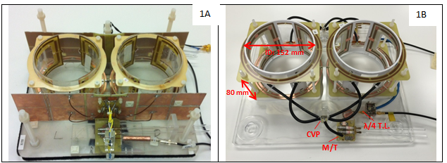
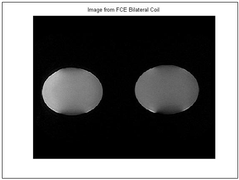
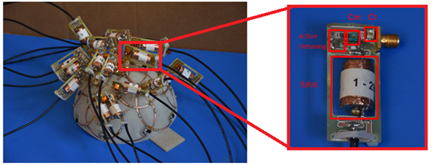
To implement FCE, quarter wavelength transmission lines (λ/4 T.L.) connected to a common-voltage point (CVP) are used to drive each coil. The currents delivered to each element are forced to be equal, independent of variations in loading or mutual coupling. This is described in detail in [10]. The FCE bilateral coil consisted of two quadrature coils, each comprised of a Helmholtz and saddle pair. Both Helmholtz and saddle pairs were connected to separate CVPs through λ/4 T.Ls. In the previously reported T/R bilateral coil shown in Fig. 1a, RF shielding was employed on either side of the coil for two reasons. 1) The shield was connected to the outside shield of the λ/4 T.L on the CVP side, and left open on the coil side, resulting in a high impedance on the coil side and avoiding the use of a balun incorporated into the λ/4 T.L (implemented using standard semi-rigid coaxial cable). 2) The connected λ/4 T.Ls formed dipole modes on the outside shield of the coaxial cable that coupled to the coil; the shield isolated the cables from the coil. While effective, the shielding was too restrictive for the insertion of a receive array and the associated hardware and cabling. In this design modified for array insertion, shielded twinaxial cables (RG108) were used as the λ/4 T.Ls. The shielded twinaxial cable allowed for balanced signal transmission and therefore eliminated the need for integrated baluns or RF shields, allowing space for the receive array integration. The coil was compared with the previous design (operated in bilateral mode) on the bench using an S21 measurement between the coil and a shielded quadrature probe input to a quadrature combiner. Imaging of a canola oil phantom was performed on a Philips 7T Achieva system, with the transmit coil operating in transmit/receive mode (sequence: THRIVE w/o fat suppression, FOV: 150 mm × 286 mm × 370 mm (AP × FH × RL), resolution: 372 × 368, TR: 4.0 ms). The 32 element receive array (2x16-channel array inserts) was designed for insertion into the transmit coil with detachable boards on each element that include the active detuning network, match and tune capacitors, and a balun.Results
The bilateral coil modified for array insertion is shown in Fig. 1b, with dimensions and the twinaxial cable addition labeled. The quadrature S21 bench measurement comparison indicated an improvement of 1.2dB in efficiency over the previous shielded version. This is at least partially due to the fact that the modified version does not include PIN diodes for switching to unilateral operation. The phantom images acquired from the coil in T/R mode are shown in Fig. 2, demonstrating homogeneous excitation. The Philips drive scale required for a 90 degree tip angle was 0.45 as compared to 0.51 for the shielded version, in agreement with the improvement in efficiency predicted by the bench measurements. The array coil is shown outside of the volume coil but with match and tune boards attached in Fig. 3, and is shown successfully integrated into the bilateral FCE coil in Fig. 4. The bilateral coil easily matched and tuned over the range required with and without the array inserted, and exhibited clean and stable S11 behavior in both cases.Conclusion
This work described the design of a forced-current-excitation quadrature coil for bilateral breast imaging, customized for the insertion of a 32-channel receive array. The use of twinaxial cable as quarter-wavelength transmission lines eliminated the need for the baluns and shielding that prevented array insertion in a previous version, and the coil efficiently generated a highly homogeneous field.Acknowledgements
1. NIH R21 EB 016394
2. P41EB015908
3. CPRIT RP150456
References
1. Korteweg MA, Veldhuis WB, Visser F, Luijten PR, Mali WPTM, et al. Feasibility of 7 Tesla breast magnetic resonance imaging determination of intrinsic sensitivity and high-resolution magnetic resonance imaging, diffusion-weighted imaging, and 1H-magnetic resonance spectroscopy of breast cancer patients receiving neoadjuvant therapy. Invest Radiol. 2011;46:370. doi: 10.1097/rli.0b013e31820df706
2. Vaughan JT, Snyder CJ, DelaBarre LJ, Bolan PJ, Tian J, et al. 7 T Whole-body imaging: Preliminary results. Magn Reson Med. 2008;61:244–248. doi: 10.1002/mrm.21751
3. Brown R, Megorty K, Moy L, DeGregorio S, Sodickson D, et al. Sub-Millimeter Breast Imaging and Relaxivity Characterization at 7T. In Proc Intl Soc Mag Reson Med 2011;3092.
4. Cheshkov S, Dimitrov I, Rispoli JV, Gonzales E, Malloy C, et al. Proton Decoupled 13C MRS of the Breast at 7T. In Proc Intl Soc Mag Reson Med 2012;1783.
5. Dimitrov I, Douglas D, Ren J, Smith NB, Webb AG, et al. In vivo determination of human breast fat composition by 1H magnetic resonance spectroscopy at 7T. Magn Reson Med. 2012;67:20–26. doi: 10.1002/mrm.22993
6. Dimitrov I, Madhuranthakam A, Cheshkov S, Seiler S, Goudreau S, et al. BreastView: Isotropic 3D High Resolution T2-weighted Breast Imaging at 7T. In Proc Intl Soc Mag Reson Med 2013;3370.
7. Klomp DW, Dula AN, Arlinghaus LR, Italiaander M, Dortch RD, et al. Amide proton transfer imaging of the human breast at 7T: Development and reproducibility. NMR Biomed. 2013;26:1271–1277. doi: 10.1002/nbm.2947
8. Pinker K, Bogner W, Baltzer P, Trattnig S, Gruber S, et al. Clinical application of bilateral high temporal and spatial resolution dynamic contrast-enhanced magnetic resonance imaging of the breast at 7T. Eur Radiol. 2014;24:913–920. doi: 10.1007/s00330-013-3075-8
9. Stehouwer BL, Klomp DW, Korteweg MA, Verkooijen HM, Luijten PR, et al. 7T versus 3T contrast-enhanced breast magnetic resonance imaging of invasive ductulolobular carcinoma: First clinical experience. Magnetic resonance imaging. 2013;31:613–617. doi:10.1016/j.mri.2012.09.005
10. McDougall MP, Cheshkov S, Rispoli J, Malloy C, Dimitrov I, et al. Quadrature transmit coil for breast imaging at 7 tesla using forced current excitation for improved homogeneity. J Magn Reson Imaging. 2014; doi:10.1002/jmri.24473.
11. By S, Rispoli JV, Cheshkov S, Dimitrov I, Cui J, Seiler S, et al. (2014) A 16-Channel Receive, Forced Current Excitation Dual-Transmit Coil for Breast Imaging at 7T. PLoS ONE 9(11): e113969. doi:10.1371/journal.pone.0113969
12. Cui J, Dimitrov I, Cheshkov S, McDougall MP, Malloy C, et al. Switchable Bilateral/Unilateral 7T Breast Coil Using Forced Current Excitation. In Pro Intl Soc Mag Reson Med 2013;2727.
Figures