2701
A novel head coil system with integrated transmission source for accurate attenuation correction in PET/MR scans1Division MR Physics - Center for Medical Physics and Biomedical Engineering, Medical Unversity of Vienna, Vienna, Austria, 2Center for Medical Physics and Biomedical Engineering, Medical Unversity of Vienna, Vienna, Austria
Synopsis
A 24 channel head and neck coil for PET/MR with an integrated moving radioactive source is presented to enable transmission measurements for accurate attenuation mapping.
Purpose
Multimodal imaging has shown to bring additional and valuable information for medical diagnostic imaging [1]. The combination of different modalities is always associated with technical and conceptual challenges, in the case of Positron Emission Tomography (PET) and MR one of these challenges is attenuation correction (AC).
We have designed a PET-optimized receive-only MR head and neck coil array. This MR coil integrates a system for AC, consisting of a point source moved hydraulically in a helical hose around the imaging coil (Fig.1). This system enables transmission measurements at 511 keV, from which accurate AC maps, including RF coil and patient, and measured at the correct energy, can be calculated.
Methods
RF coil: the coil array consists of 24-channels distributed in 4 rows with 3/7/7/7 elements (Fig. 2a). There are 17 quadratic elements (9.5cm x 9.5cm) and 7 trapezoidal elements (9cm/5cm x 10.5cm). Within rows, transformer decoupling was implemented, while neighboring rows were decoupled by overlapping the elements. Balun matching networks and preamplifier decoupling were implemented for all channels. The strongly attenuating components like preamplifiers were placed outside the PET field-of-view as recommended for PET-MR coils [3] and thin (0.75 mm diameter) copper wire was used for the coil elements. A photo of the final construction is shown (Fig.2b).
The coil housing was designed using 3D CAD software, and 3D-printed from laser-sintered polylaurinlactam. The MR coil is built on an elliptical inner former, where the elements and the electronics were placed. This inner former is inserted in a cylindrical outer shell acting both as cover for the RF coil and to support the hydraulical system, leaving free space for the shoulders. The housing thickness was minimized while maintaining stability, with a maximum wall thickness of 4 mm.
MR images (3D GRE, TR/TE=30/2.39 ms, FA=15°, in plane resolution=0.56x0.56 mm2, slice thickness=1.4 mm, MA=640x640x256) of a gel head phantom (1% Agarose, 65 µmol/kg Magnevist, 0.1% NaCl, and 0.05% NaN3) were acquired. S-parameters of the coil were measured using a network analyzer with multiport test set (Agilent Technologies, E5071C/E5092A). To obtain noise correlation information, noise data was acquired using a free induction decay sequence without RF excitation. Raw data was post-processed with in-house developed MATLAB scripts.
Hydraulical system: the information about the position of the point source (pellet) will be synchronized with the PET list-mode data during acquisition using optical triggers distributed around the cylindrical outer shell. This should allow simplified and improved reconstruction of the transmission image. Currently the hose is filled with distilled water, in the final implementation it will be exchanged by heavy water, avoiding MR signal from the hose.
Monte-Carlo simulations (Geant4 Application for Tomographic Emission, GATE [4]) were performed to determine global scatter-fraction on a virtual head phantom (Duke, Virtual Population, IT'IS Foundation) placed in a model of the RF coil and the transmission system. For the source, a 20 MBq pellet was used.
Results
Images of the phantom acquired in the complete set up, using distilled water, are shown in Figure 2. S-parameters and the noise correlation matrix are shown in Figure 3.
For the attenuation correction method, Monte-Carlo simulations showed that the loss in photon global scatter-fraction of the entire hardware set-up including a realistic head phantom is 16.4%, enabling PET reconstruction with standard algorithms.
Conclusion
An RF coil is presented for a combined hardware set-up for PET/MR measurements of the head and neck, integrating AC mapping and MR acquisition in a single device. First images of the complete system are presented together with S-parameters and noise correlation matrix. First simulations results are also included.Acknowledgements
Financial support of the Austrian FWF Projects P27853-B30 and P28867-B30 are gratefully aknowledge.References
[1] Wehrl et al., J Nucl Med 2015.
[2] Keereman et al., Magn Reson Mater Phys 2013.
[3] Sander et al., Magn Reson Med 2015.
[4] Jan et al. Phys. In Med. 2004
Figures
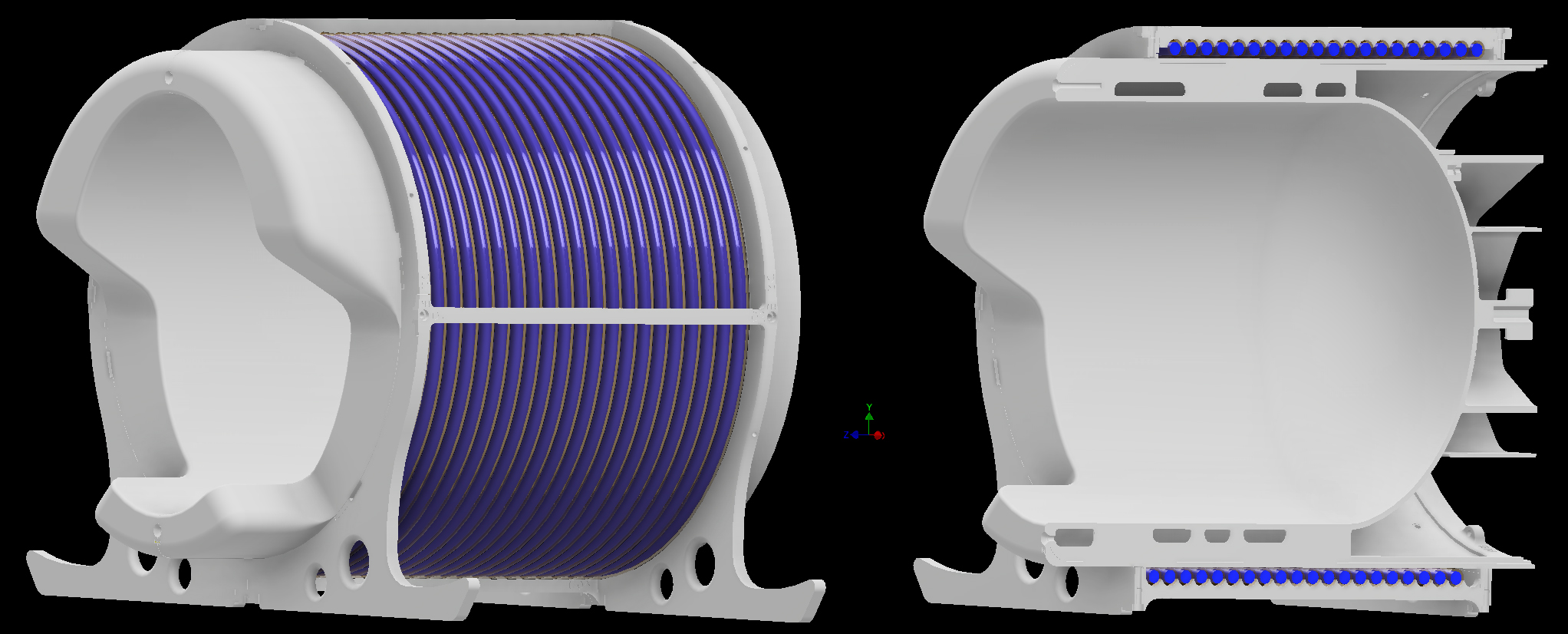
Figure 1: Coil housing.
The elliptical inner former is 26.5 cm high, 21 cm wide, and 23 cm long; closed by an ellipsoidal cap of 9.4 cm height. The cylindrical outer former has a diameter of 32 cm. The hose for the circulating radioactive point source is shown in blue.
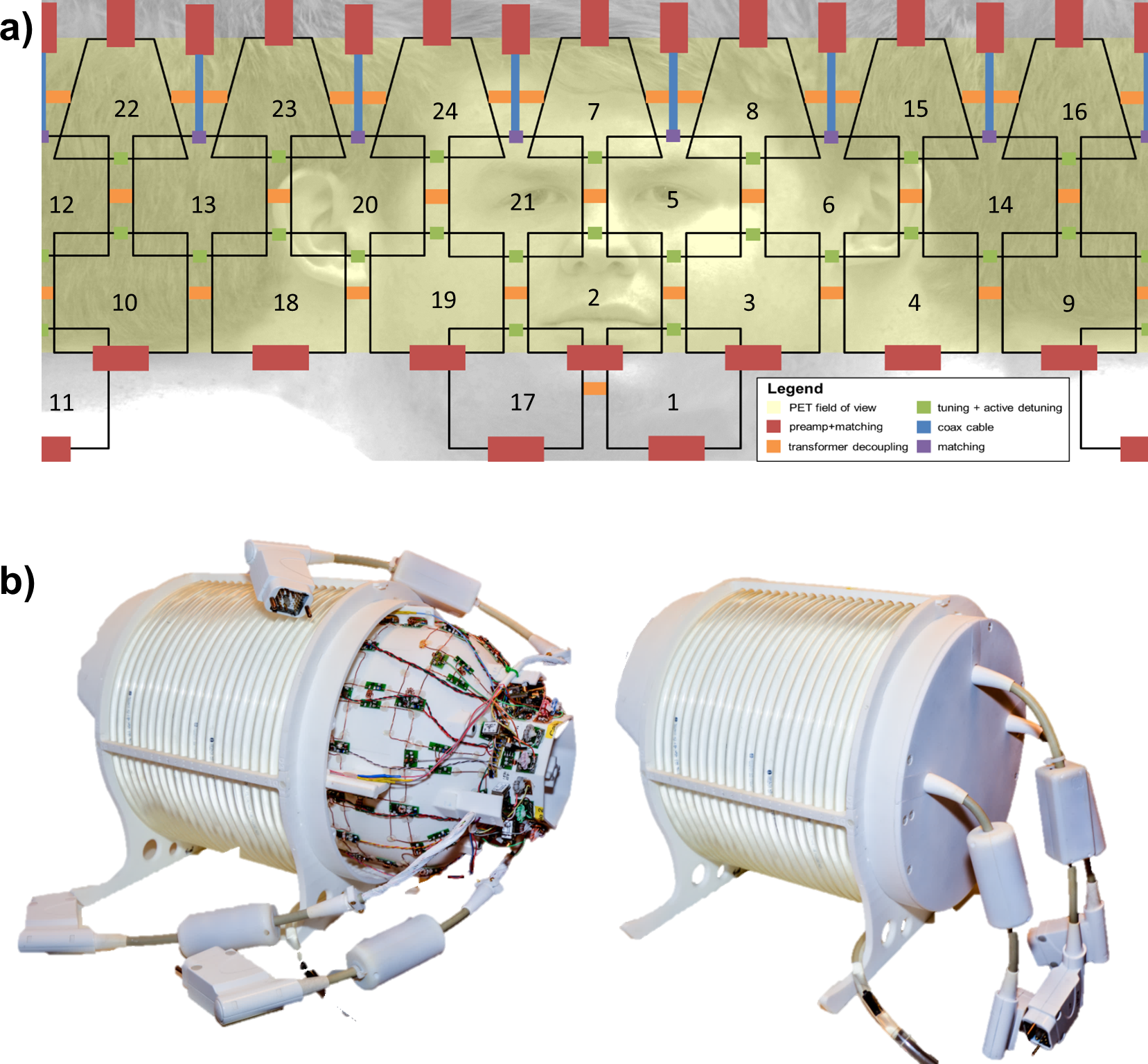
Figure 2: RF coil layout and implementation.
a) 24 channel coil array layout. 17 square elements distributed in three rows with mesure 9.5 cm x 9.5 cm. The top row consists of 7 trapezoidal elements arranged over the top curved part of the coil. The size of these elements are base width of 9 cm, height of 10.5 cm and top width of 5 cm. b) Photos of the developed MR head and neck coil together with the transmission system (opened and closed).
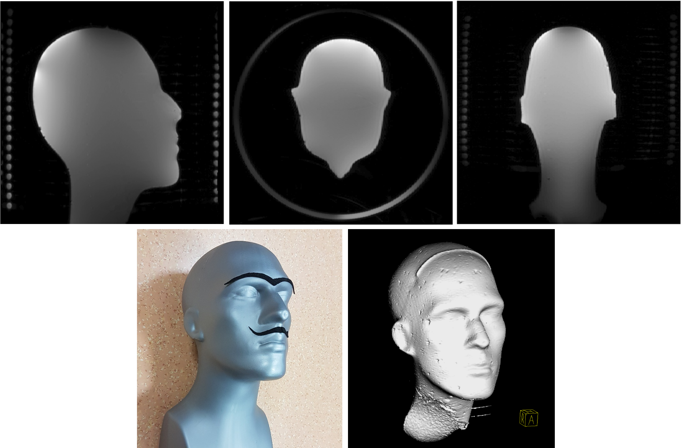
Figure 3: Phantom MR images.
Top) 3D GRE gel phantom images, showing also the hose of the hydraulic system currently filled with distilled water Bottom) Photograph and 3D MR data visualization of the head phantom used.
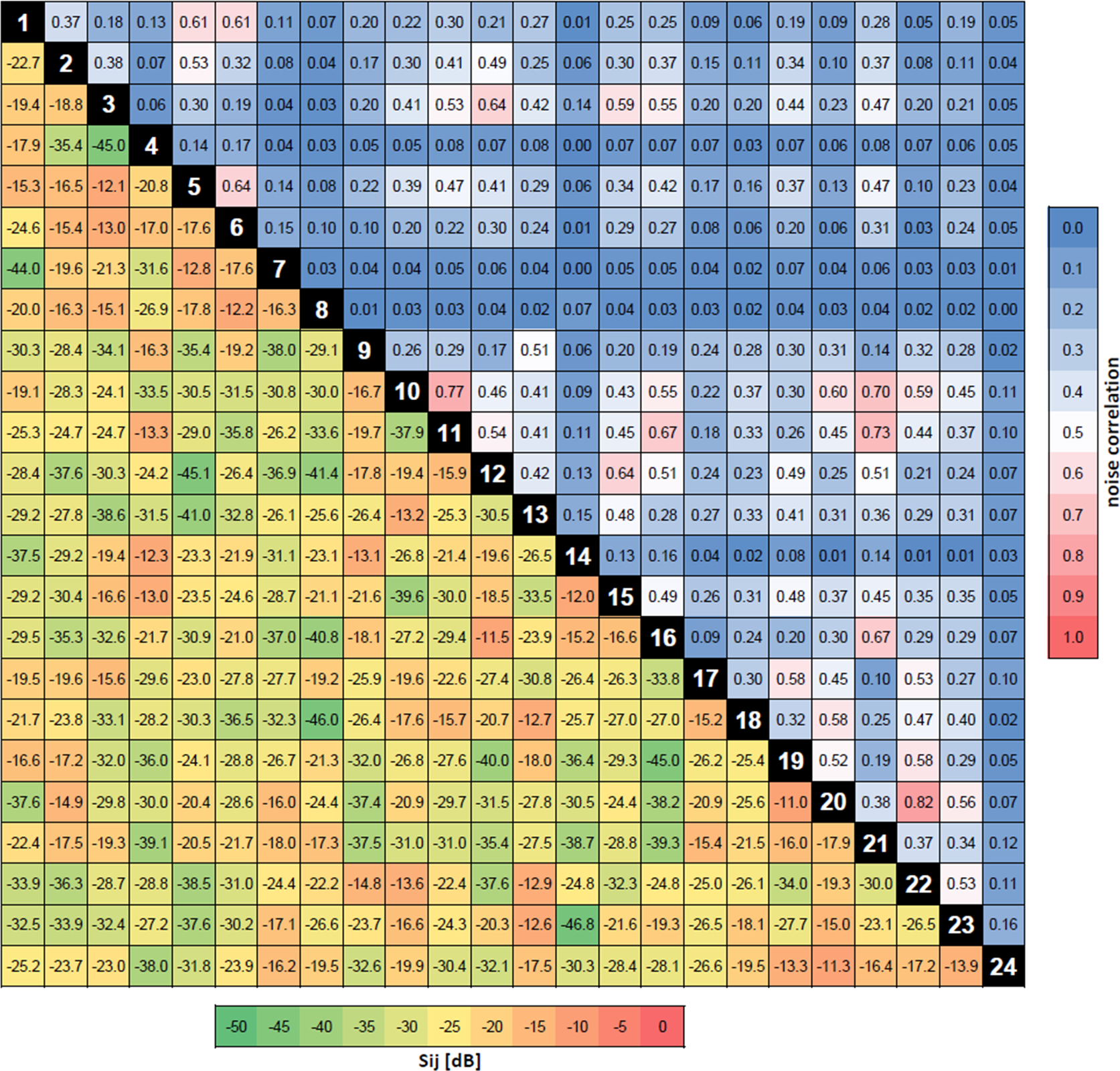
Figure 4: Coil characteristics.
Bottom/left) S-parameter matrix. Sij measurements for each channel pair terminating all other channels with 50 Ω and loaded by the phantom. Top/right) Noise correlation matrix. The coil array was loaded by the phantom.