2700
RF Power Considerations for Simultaneous Multi-Nuclear MRI/MRS1Electrical & Computer Engineering, Texas A&M University, College Station, TX, United States
Synopsis
There are many approaches to simultaneous multi-nuclear spectroscopy, but the simplest and potentially the most elegant involves sending all frequencies through a single broadband amplifier into a single-port, multi-tuned coil. This abstract examines a complication in this approach, that of early saturation of the amplifier due to the need to amplify two signals simultaneously. A simple solution, staggering the RF pulses a small amount to avoid the overlapping of their peaks, is shown to largely avoid the problem.
Purpose
Simultaneous magnetic spectroscopy of different nuclei has been suggested by researchers dating back to at least the 1980s [1]. Recently there has been renewed interest in this topic, driven by research in spectroscopy from hyperpolarized species and related issues in quantitation. There are many approaches to simultaneous multi-nuclear spectroscopy, but the simplest and potentially the most elegant involves sending all frequencies through a single broadband amplifier into a single-port, multi-tuned coil. This abstract examines a complication in this approach, that of early saturation of the amplifier due to the need to amplify two signals simultaneously. A simple solution, staggering the RF pulses a small amount to avoid the overlapping of their peaks, is shown to largely avoid the problem.Methods
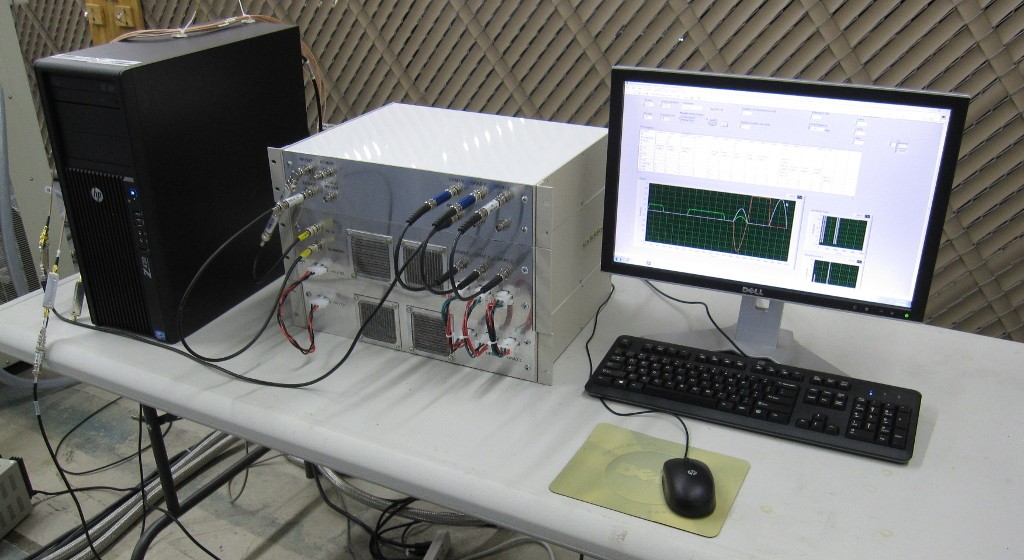
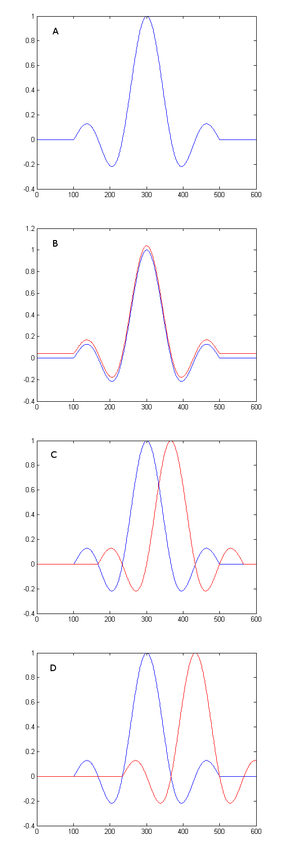
A broadband NMR spectrometer (Fig. 1) was assembled for true simultaneous multinuclear transmit and receive. The pulse sequencer employed a National Instruments PCI-6363 DAQ card to provide analog outputs and digital control. The system was capable of simultaneously generating as many as four RF pulses at different frequencies simultaneously using an Analog Devices 9959 direct digital synthesizer. The system similarly had a very broad band (700 MHz) receiver, using a four channel Ultraview AD16-250. Software was written in LabVIEW to perform an RF pulse calibration on a single nucleus while holding the RF output power at the other frequencies constant. For purposes of this experiment, a double tuned coil was used, tuned simultaneously to 2H and 23Na at 4.7T (30 and 53 MHz). Initially, no power was applied at 2H and a calibration curve for 23Na was obtained, tip angle vs. RF power as measured in dB of attenuation. Next, the 23Na was calibrated again while simultaneously applying a high power sinc pulse at 2H. This was repeated with the 2H sinc pulse offset from the 23Na pulse by half the width and the entire width of the main lobe of the sinc pulse, as seen in Figure 2.
A 4 ms sinc pulse with 5 lobes was used for both nuclei, giving a main lobe width of 1.33 ms. Approximately 200W of power was necessary to achieve a 90 degree tip in 23Na (with no 2H excitation) and a 700W 2H pulse was applied (lower gyromagnetic ratio nuclei require more current to achieve the same tip angle). All data was collected on a 4.7T/33 cm magnet.
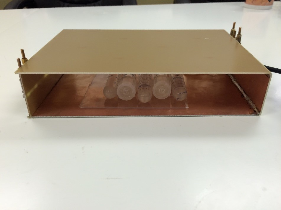
A dual tuned 2H and 23Na coil, had been previously constructed [2-4]. Both frequencies are tuned and matched at a single port, allowing for the use of a single transmit and receive path. This makes it possible to switch the nuclei under study by simply changing a setting on the spectrometer. No retuning or switching of cables is required.
Results
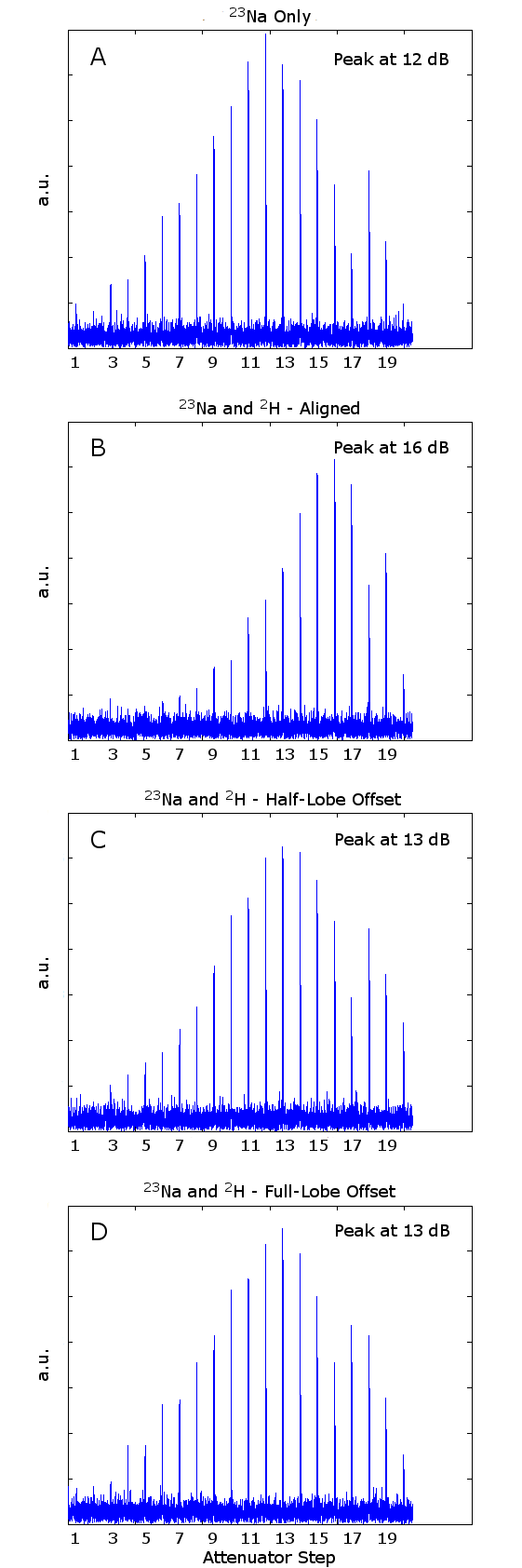
The reference RF calibration curve with only a 23Na pulse is shown in figure 3a. Figure 3b shows the curve with simultaneous pulses on 23Na and 2H. Figures 3b and 3c show the same with the RF pulses for 2H shifted. As expected, the RF calibration curve with 23Na alone demonstrates the expected sinusoidal behavior, indication constant amplifier gain with increasing input power. With the 2H power applied, the calibration curve is distorted, requiring greater input power to reach the same tip angle, indicating saturation of the amplifier at the 180 degree pulses. The calibration curves with shifted RF pulses are much closer to the original curve, even when the pulse is only shifted by the width of a side lobe.Discussion
Offsetting the RF pulses of a simultaneous excitation is a straightforward way to reduce the change in the gain of the RF power amplifier when transmitting multiple nuclei. For a 4 ms sinc pulse with 5 lobes, even offsetting by 660 us is enough to reduce the change in the gain of the RF amplifier by 3 dB. For a spin echo sequence slice rephrasing is not impacted by the offset. Self-refocusing RF pulses could be used to extend this technique to gradient echo sequences. Note that this does not change the TE for either acquisition. One minor issue is that this approach applies a chemical shift dependent phase shift, similar to the Dixon method, onto the spectra at the nucleus with the shifted RF pulse. For many nuclei, including 23Na,chemical shifts are rare in naturally ocurring substances, so this problem is easy to avoid.Acknowledgements
This work was supported in part by grants from the National Institutes of Health (R21HL120064) and the Cancer Prevention and Research Institute of Texas (RP15046)References
[1] O. Gonen, et al., JMR B, vol. 104, pp. 26-33, 1994.
[2] J. Murphy-Boesch, “Double Tuned Birdcage Coil: Construction and Tuning,” eMagRes, pp. 1–7, 2011.
[3] H. Dong, et al., IEEE Engineering in Medicine and Biology Conference Orlando 2016
[4] B. Taber et al., JMR, vol. 259, pp. 114–120, 2015.
Figures