2699
Experimental study for efficient RF-penetration through electrically-floating PET insert for MRI systems1National Institute of Radiological Sciences, Chiba, Japan, 2Radiology, Stanford University, CA, United States, 3Chiba University, Chiba, Japan
Synopsis
PET inserts for the existing MRI systems are showing great potential for widespread and affordable low-cost simultaneous PET/MR imaging that would otherwise improve the PET sensitivity due to the proximity of detectors to the imaging region. To avoid electromagnetic interference between PET and MRI components, PET detectors are enclosed in Faraday shield cages. A electrically floating PET insert enables us to use MRI built-in body RF coil instead of using separate custom designed RF coil with the PET insert. This study experimentally evaluates different PET geometries and different design factors for efficient RF penetration through the floating-PET insert.
Introduction
According to the implementation of RF transmit/receive (Tx/Rx) fields, PET inserts for existing MRI systems can be categorized into three types: (a) PET-ring with separate Tx/Rx coil [1], (2) PET-ring integrated with Tx/Rx coil [2], (3) PET-ring that uses built-in body coil as Tx and/or Rx [3]. In the third category, it is needed to keep the shielded PET-ring electrically floating from RF-ground to let the field penetrate through the gaps given in PET geometry. In previous studies [4-5] we gave results on a floating oval-insert in which we showed that partial-ring geometries have much better RF-penetration than full-ring geometry. In this study we conducted experiments on different design issues of full-ring PET geometry, like, shield box shape, inter-shield-box gap, ring-length, multi-ring PET geometry for efficient RF (B1) penetration.Methods and Materials
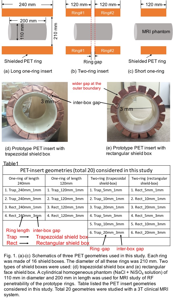
In this study, cylindrical one-ring and two-ring prototype shielded PET inserts of diameter 210mm were considered for performing experiments in a 3T clinical MRI system (Siemens MAGNETOM Verio) with a cylindrical homogeneous phantom (NaCl+NiSO4 solution) of diameter 110mm and axial-length 200mm. The shield boxes were made with 18mm thick copper (Cu) foil. Sixteen such shield-boxes were arranged in cylindrical ring format for one-ring and 32 shield-boxes for two-ring insert. This initial study did not include any PET detectors. Details specifications are given below:
One-ring insert of axial-length:
1. 240mm (Fig.1(a))
2. 120mm (Fig.1(b))
Two-ring insert of ring-gaps (Fig.1(c)):
1. 5mm
2. 10mm
3. 20mm
Shapes of shield-boxes (Figs.1(d)-(e)):
1. trapezoidal shield-box (Fig.1(d))
2. rectangular shield-box (Fig.1(e))
Inter-shield-box gaps (Figs.1(d)-(e)):
1. 1mm
2. 3mm
In total, 20 different PET-ring configurations (as listed in Fig.1) were considered for experimental study for B1 field and SNRs of spin-echo (SE) and gradient-echo (GE) images. For the B1 field (double-angle method [6-7]), SE parameters were: TR=3000ms, TE=12ms, Slices=12 for transverse and 10 for coronal, flip-angle=600/1200, refocusing-angle=1800. Sequence parameters for SNR [8] of SE and GE images were: TR=600ms, TE=12ms, flip-angle=900, refocusing-angle for SE=1800, slices=7, Slice-thickness=5mm.
Results
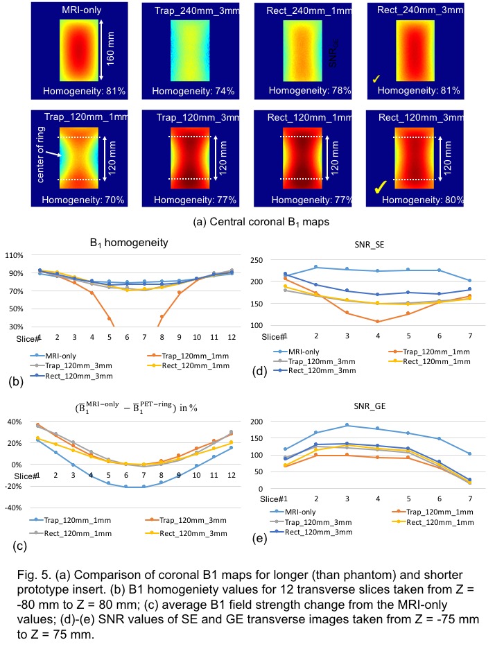
Results for the 240mm long one-ring insert are illustrated in Fig.2. For ‘Trap_240mm_3mm’ insert, B1 homogeneity and field-strength were very low, whereas ‘Rect_240mm_1mm’ and ‘Rect_240mm_3mm’ inserts exhibited significant improvement.
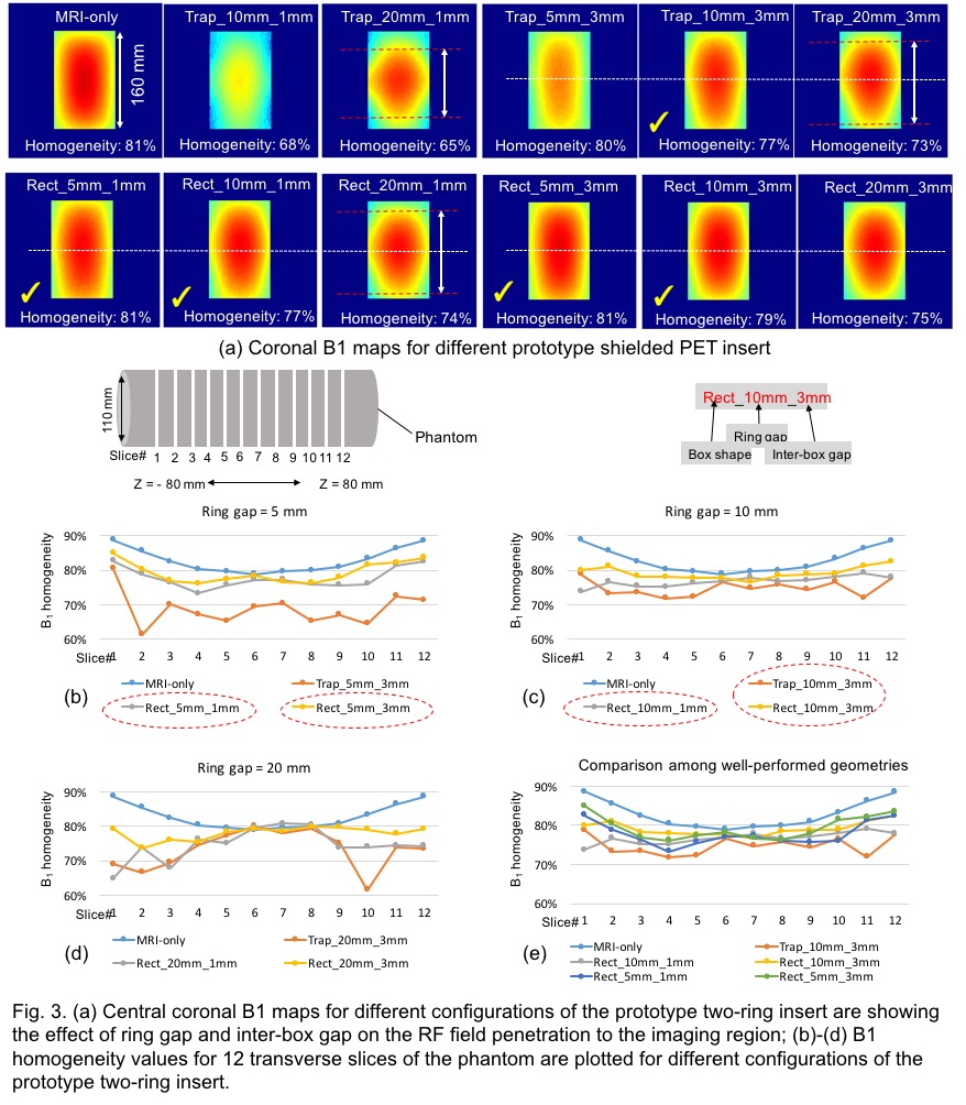
Results of B1 field for the two-ring inserts are illustrated in Fig.3. From coronal B1 maps, it is clearly seen that for 20mm ring-gap (white dotted-line region), RF-field concentrated mostly near the ring-gap region that reduces the B1 homogeneity and field strength near the end-faces as is also clearly seen from transverse B1 homogeneities given in Fig.3(d). Also all rings with rectangular shield-box exhibited high RF-penetration compare to trapezoidal box (Figs.3(b)-(e)). ‘Rect_5mm_3mm’ and ‘Rect_10mm_3mm’ exhibited highest performances.
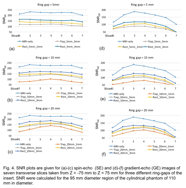
Also, almost uniform SNRs were seen for the 5mm and 10mm ring-gaps (Fig.4). Rectangular shield-box showed better SNR than trapezoidal shield-box.
Fig. 5 illustrates results for the 120mm long one-ring geometry and compares with the 240mm long one-ring geometry. From the second row, it is seen that field near the center of shield-box region is significantly low. On the other hand, field outside the rings (120mm) becomes very high compare to MRI-only and 240mm long one-ring insert. The homogeneity values, field strength and SNR values (Figs. 5(b)-(e)) also confirms this observation.
Discussion
The MRI system could not generate images for one-ring ‘Trap_240mm_1mm’, two-ring ‘Trap_5mm_1mm’ due to very weak RF-penetration. Considering all of the other 18 ring configurations, it is well proved that the rectangular box performed much better than trapezoidal box even with narrow inter-box gaps. On the other hand, within the 160mm axial-extent in the coronal plane, for a shorter-ring (e.g., 120mm) comparatively strong and highly homogeneous RF field is seen outside the ring – average B1 field-strength increased by more than 30%. It is not sure whether this would also generate high SAR. We plan to study on this in the coming days. Also two-ring inserts performed better than 240mm long one-ring insert. For large scale design we plan to use separate Rx coil inside the PET insert. In such case SNR values would increase to greater extent.Conclusion
In this study we conducted experiments on different full-ring PET geometries and also different design factors of PET-ring geometry for efficient RF-penetration inside the electrically-floating PET inserts for acceptable MRI performances. For efficient RF-penetration rectangular shield-box should be used. If possible, multiple-ring PET geometry should be introduced. The wider inter-box gap results in higher RF-penetration. And axial-length of ring is an important design factor that should be carefully checked to avoid over-excitation of the flip-angle and possible higher SAR values near the end-faces of the PET-ring.Acknowledgements
No acknowledgement found.References
[1] A. Kolb, H.F. Wehrl, M. Hofmann, et al., Technical performance evaluation of a human brain PET/MRI system, Eur. Radiol. 22 (2012) 1776–1788. doi: 10.1007/s00330-012-2415-4
[2] F. Nishikido, T. Obata, K. Shimizu, et al., Feasibility of a brain-dedicated PET-MRI system using four-layer DOI detectors integrated with an RF head coil, Nucl. Instr. Meth. Phys. Res. A 756 (2014) 6–13. http://dx.doi.org/10.1016/j.nima.2014.04.034
[3] P. Olcott, E. Kim, K. Hong, et al., Prototype positron emission tomography insert with electro-optical signal transmission for simultaneous operation with MRI, Phys. Med. Biol. 60 (2015) 3459–478. doi: 10.1088/0031-9155/60/9/3459
[4] Md Shahadat Hossain Akram, Craig S. Levin, Takayuki Obata, et al., Concept of an RF penetrable oval PET insert for MRI system: initial study of the shielding effect, ISMRM (The International Society for Magnetic Resonance in Medicine), Singapore, 7-13 May, 2016
[5] Md Shahadat Hossain Akram, Craig S. Levin, Takayuki Obata, et al., An RF-penetrable oval body PET insert for MRI: initial experimental study for efficient MR imaging performance, Conference Record IEEE NSS-MIC, M16E-9, 2016.
[6] R. Stollberger, P. Wach, G. McKinnon, et al., RF field mapping in vivo, Abstracts of the Society of Magnetic Resonance in Medicine, 7th Annual Meeting (1988) p.106.
[7] E.K. Insko, L. Bolinger, Mapping of radiofrequency field, J. Magn. Reson. Series A 103 (1993) 82-85.
[8] L. Kaufman, D.M. Kramer, L.E. Crooks, D.A. Ortendahl, Measuring signal-to-noise ratios in MR imaging, Radiology 173 (1989) 265-267.
Figures