2698
Control of an MRI-Guided Magnetically-Actuated Steerable Catheter System1Electrical Engineering and Computer Science, Case Western Reserve University, Cleveland, OH, United States, 2Biomedical Engineering, Case Western Reserve University, Cleveland, OH, United States, 3Mechanical and Aerospace Engineering, Case Western Reserve University, Cleveland, OH, United States, 4Radiology, University of Hospitals of Cleveland, Cleveland, United States
Synopsis
This paper presents a Jacobian-based inverse kinematics and open-loop control method for an MRI-guided magnetically-actuated steerable intravascular catheter system. The catheter is directly actuated by magnetic torques generated on a set of current-carrying micro-coils embedded on the catheter tip by the magnetic field of MRI scanner. The Jacobian matrix is derived from a three dimensional kinematic continuum model of the catheter deflection. The inverse kinematics are numerically computed by iteratively applying the inverse of the Jacobian matrix. Experimental evaluation compares a catheter prototype’s desired trajectory to the actual trajectory.
Purpose
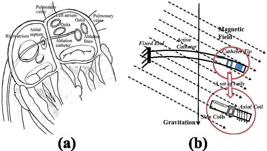
The proposed MRI-guided magnetically-actuated steerable intravascular catheter will assist cardiac ablation to treat atrial fibrillation1-3 (Fig. 1a). The catheter body is directly actuated by magnetic torques. Current-carrying micro-coils embedded on the catheter body interact with the magnetic field of MRI scanner to generate the magnetic torques (Fig. 1b). The catheter system is not subject to the mechanical transmission problems that exist in other actuation methods (such as tendon-driven4 and hydraulic5 actuation). Consequently, this magnetic actuation method increases the bandwidth of the system by reducing backlash and friction. Currently, accurate control of the catheter tip position poses a challenge. Here, an open-loop control method using Jacobian-based inverse kinematics is presented. This method will help the physicians by facilitating intuitive control of the catheter while precisely moving the catheter to the desired ablation targets on the atrial wall6-7.Methods
The deflection of the catheter is controlled by the amount of the current going through these electromagnetic coils. Liu et al.3 developed a method where a finite differences approach is combined with beam theory and rotation groups to model the three dimensional deflection of the proposed catheter. The deflection includes bending and torsional motions. In the present study, the Jacobian matrix (J) relating changes of the currents through the coils (i) to changes of the tip position (P) is derived. As a closed form expression that directly relates the tip position to the actuation currents is not available, the Jacobian is computed indirectly as $$$J = \frac{dP}{dX}\frac{dX}{di}$$$, from the kinematic model of the catheter tip position as a function of deflection angles (X), and the three dimensional deflection model of the catheter3 relating the actuation currents and the deflection angles. The inverse kinematics is then numerically computed by iteratively applying the inverse of the Jacobian matrix. During the iteration, a damped least square method is used to avoid numerical instability during computation of the Jacobian matrix’s inverse. Given a desired trajectory for the tip of the catheter, the current corresponding to each point on the trajectory is calculated using the proposed Jacobian-based inverse kinematics method. The estimated trajectory currents are subsequently used to actuate the catheter.Results
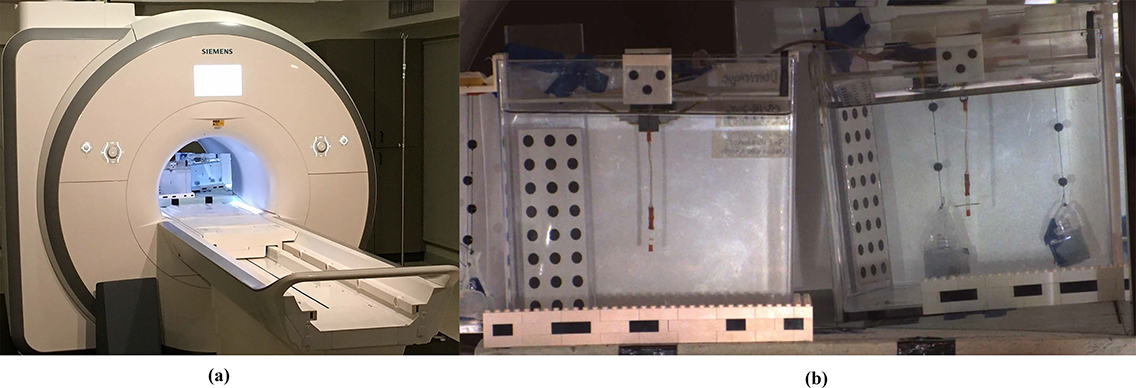
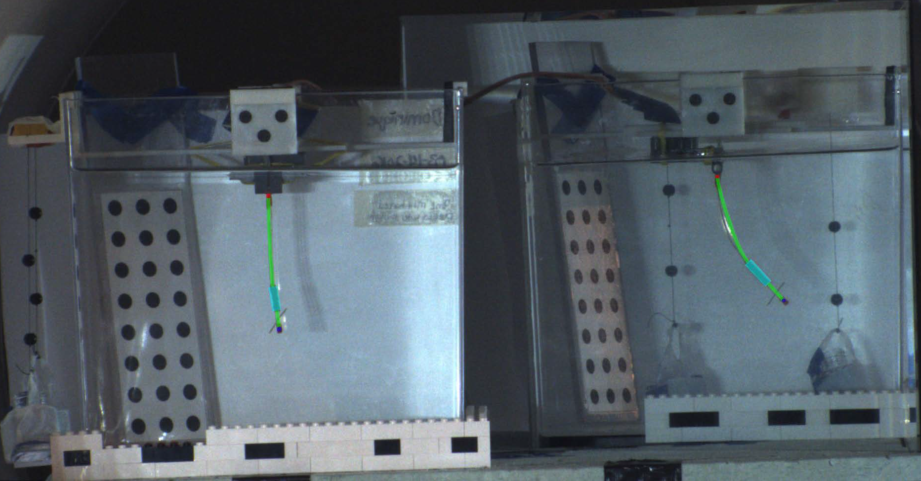
The experiments to validate the proposed method are conducted in a 3T clinical scanner (Skyra, Siemens Medical Solutions, Erlangen, Germany). The experimental setup is shown in Fig. 2. The catheter prototype is mounted vertically inside an aquarium tank and immersed in a phantom filled with distilled water doped with a gadolinium-based contrast agent. One current-carrying coil set, consisting of one 100-turn axial coil and two 30-turn orthogonal side coils, is embedded on the catheter. The catheter is tracked by a catadioptric digital camera system (Fig. 3).
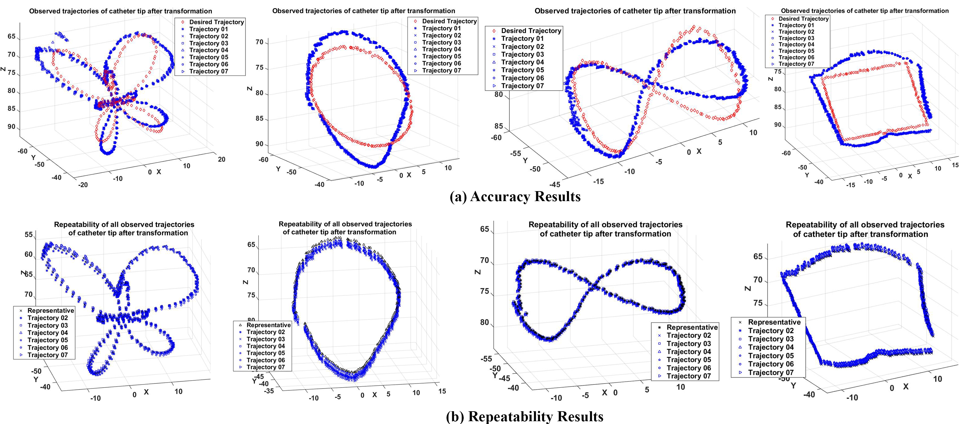
Four distinct trajectories (butterfly, circle, lemniscate, and square) are used for evaluating the performance of the control. These trajectories, consisting of 200 set currents each, are chosen because of their similarity to the circumferential and linear ablation lesions employed in atrial fibrillation ablation6. Each trajectory shape is recorded 7 times during the experiments. As the presented control scheme is open-loop (which does not use any feedback from measurement of catheter position), offset and drift type errors between the desired and observed trajectories are expected. Therefore, shape repeatability of the trajectories (allowing the trajectories to be translated and rotated, but not scaled) is used as the error metric.
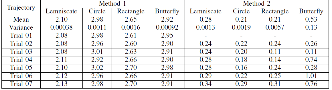
Fig. 4a shows the shape comparisons between the given desired trajectory of the tip (red) and the observed trajectories which are transformed without scaling (blue). Additionally, the repeatability (Method 2) is also computed by comparing one of the measured trajectories randomly selected as a reference trajectory, and shapes of the other measured trajectories (Fig. 4b). The root-mean-square (RMS) of the errors between desired and observed catheter tip trajectories are reported in Table I.
Discussion
The low mean and variance values for the RMS errors indicate very good repeatability of the trajectory shapes. In other words, the overall shape of the observed trajectory is similar to the corresponding trajectory pattern provided, even for complicated patterns, such as the butterfly pattern. The resulting repeatability error is not sensitive to offset (and some drift) types of errors that are inherent to open-loop control schemes, and can easily be eliminated by either physician-in-the-loop or closed-loop control of the catheter.Conclusion
The repeatability results demonstrate that the proposed open-loop control can actuate the catheter to successfully perform complex ablation trajectories required for atrial fibrillation ablation. This study paves the way for effective and accurate closed-loop control of the robotic catheter with real-time feedback from MRI guidance in subsequent research.Acknowledgements
NSF IIS 1524363, NSF IIS 1563805, and NIH R01 EB018108.References
1. T. P. L. Roberts et al., “Remote control of catheter tip deflection: An opportunity for interventional MRI,” Magn. Reson. Med., vol. 48, no. 6, pp. 1091–1095, 2002.
2. N. Gudino et al., “Control of intravascular catheters using an array of active steering coils,” Med. Phys., vol. 38, no. 7, pp. 4215–4224, 2011.
3. T. Liu, N. L. Poirot, D. Franson, N. Seiberlich, M. A. Griswold and M. C. Çavusoglu, "Modeling and Validation of the Three-Dimensional Deflection of an MRI-Compatible Magnetically Actuated Steerable Catheter," in IEEE Trans. Biomed. Eng., vol. 63, no. 10, pp. 2142-2154, Oct. 2016.
4. Sensei® X Robotic Catheter System, Hansen Medical, http://www.hansenmedical.com/.
5. K. Ikuta, H. Ichikawa, K. Suzuki, and D. Yajima, “Multi-degree of freedom hydraulic pressure driven safety active catheter,” in Proc. IEEE Int. Conf. Robot. Autom., May 2006, pp. 4161–4166.
6. J. Dewire and H. Calkins, “State-of-the-art and emerging technologies for atrial fibrillation ablation,” Nat. Rev. Cardiol., vol. 7, pp. 129–138, 2010.
7. J. D. Burkhardt and A. Natale, “New technologies in atrial fibrillation ablation,” Circulation, vol. 120, no. 15, pp. 1533–1541, 2009.
8. R. C. Jackson, T. Liu, and M. Cavusoglu, “Catadioptric stereo tracking for three dimensional shape measurement of MRI guided catheters,” in Proc. IEEE Int. Conf. Robot. Autom., May 2016.
Figures