2692
Wireless Clock Transfer for MRI Phase Correction1Electrical Engineering, Stanford University, Stanford, CA, United States, 2Procyon Engineering, Stanford, CA, United States, 3Advanced Coils, GE Healthcare Inc, Aurora, OH, United States
Synopsis
One step in making wireless MRI possible is to sync the clocks at both the transmit side hardware that plays out the pulse, and the receive chain that processes the FID data. A discrepancy between the timing of the two clocks will lead to jitter that amounts to artifacts in the MRI image. In this work, we demonstrate a method to transfer a wireless clock without creating jitter artifacts in an MRI image.
Introduction
The path to making an MRI receiver coil completely wireless requires a variety of steps including a means of wirelessly detecting the scanner state to activate/deactive Q-spoiling and start readout, transmitting the MRI data set, and finally synchronizing the clock of the receive coil electronics with the clock of the transmit hardware. This abstract addresses the final point. It is necessary to synchronize the sampling clocks between the hardware at the transmit side of the scanner and the receive side of the scanner during pulse-sequence play-out. Having the MRI transmit and receive hardware architectures run on separate clocks would result in accumulated phase error in the collected data, which causes image artifacts. MRI is a phase sensitive application and methods for correcting such phase errors have been explored [1].
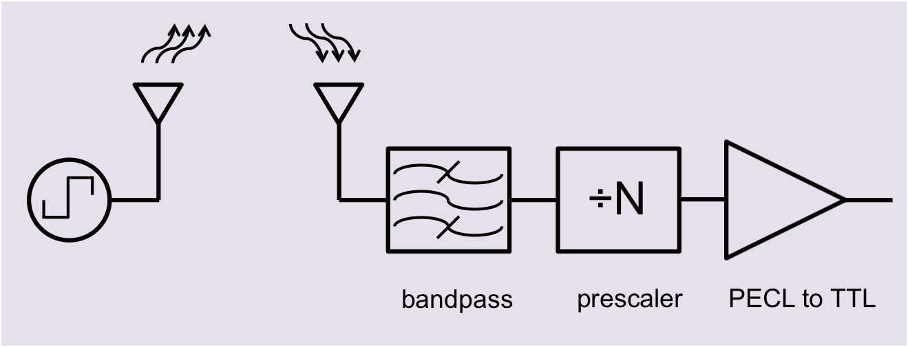
This work demonstrates the wireless transfer of a clock signal that will be frequency locked and converted to a high frequency signal (1.6 GHz) at the transmit end. This allows a reduction in the antenna size. The clock is transmitted wirelessly before being divided down to the original clock frequency at the receive end. Figure 1 shows a high level block diagram.
Materials and Methods
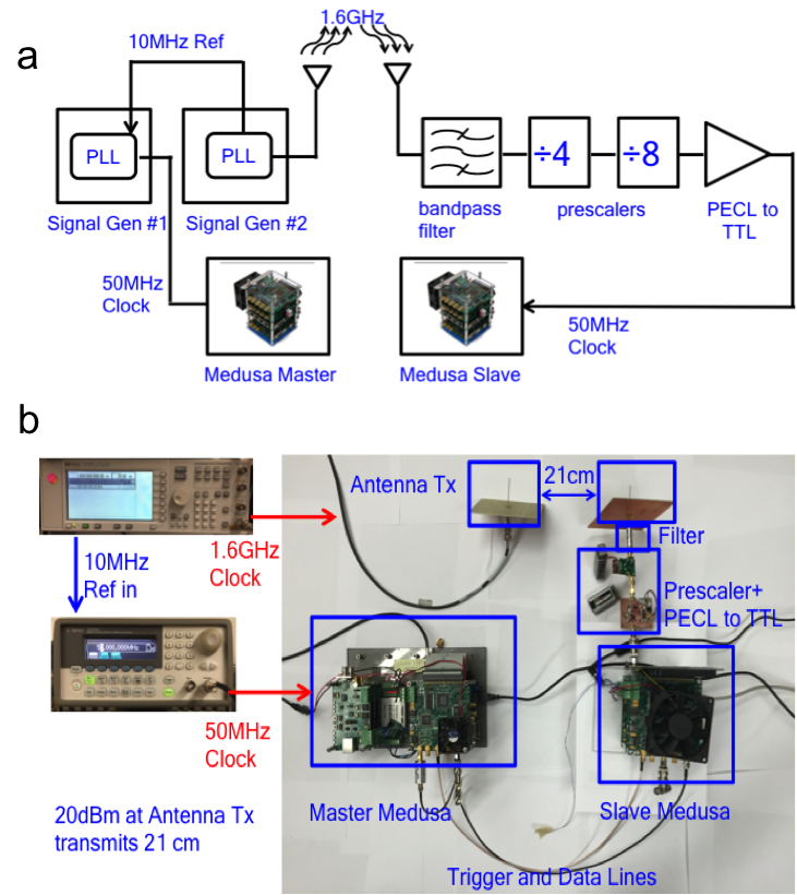
We demonstrated wireless clock signal transfer by synchronizing the clocks of two separate Medusa consoles [2]. Both Medusas run at 50 MHz sampling clocks. An Agilent 33250A signal generator provided a 50MHz clock for the master Medusa. The Agilent 33250A signal generator was frequency locked to an HP E4420B signal generator when connected to the latter’s 10 MHz reference output. The HP EE4420B then generated a clock signal at 1.6GHz locked to the 50MHz clock of master Medusa. This 1.6GHz clock signal was transmitted across two monopole antennas, each of length 4.7cm with a power level of 20dBm and 21 cm separation.
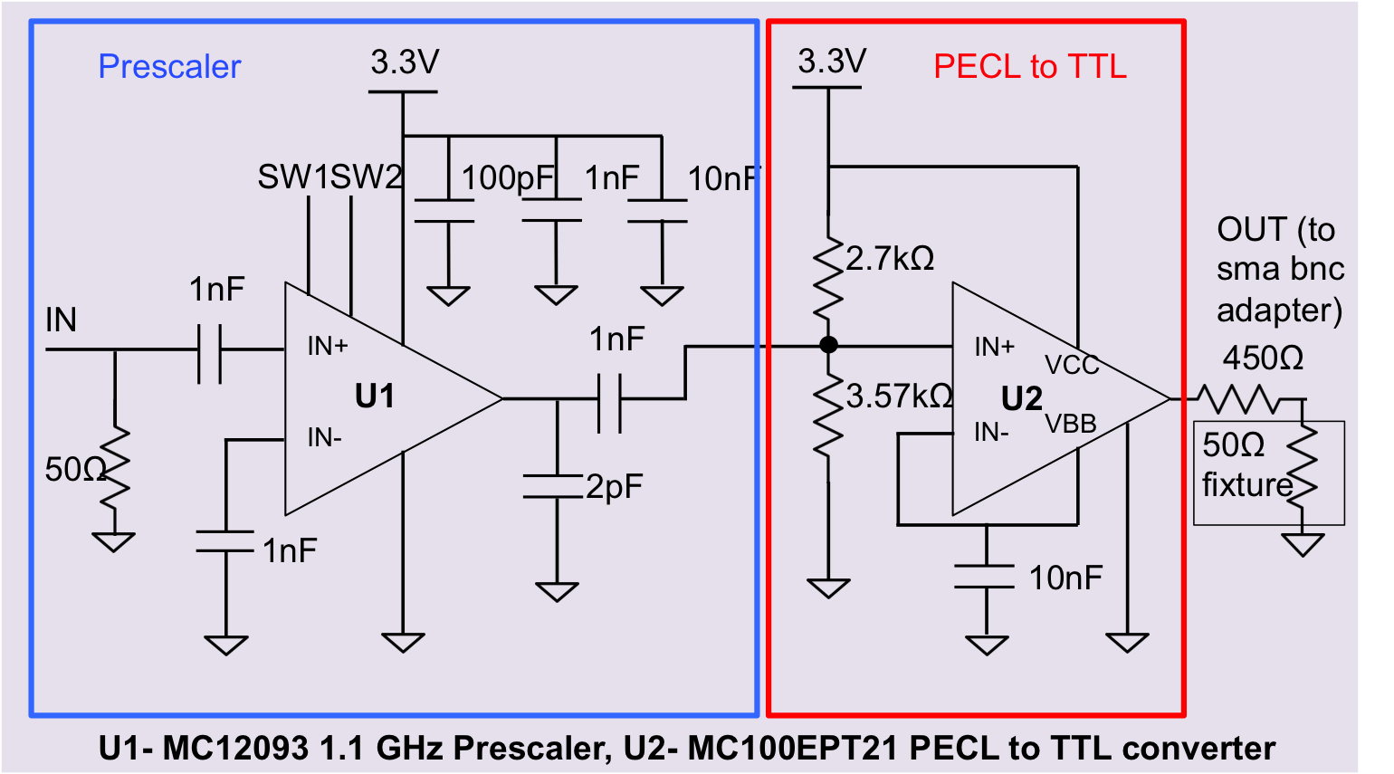
At the receive antenna, the wirelessly transmitted clock signal was filtered, divided down by prescalers (parts HMC433 and MC12903) to 50MHz, and level-converted through a PECL to TTL driver (MC100EPT21) before being converted to a TTL signal that served as a clock for the slave Medusa. The HMC433 was provided on a demo board. The schematic for the MC12903 and MC100EPT21 prescaler is shown in Figure 2.
In our setup (Figure 3), a k-space data stream mimicking a phantom image could be sent from the master to the slave in tandem with the wireless clock and evaluated for artifacts. The master Medusa sent one line of k-space data with each TR, and the slave Medusa was programmed to acquire each line after receiving a trigger signal from the master.
Results and Discussion
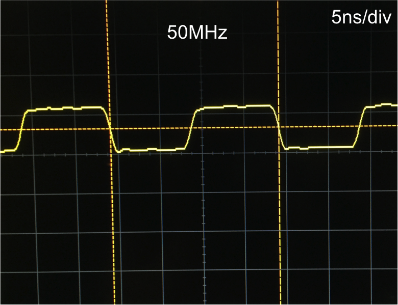
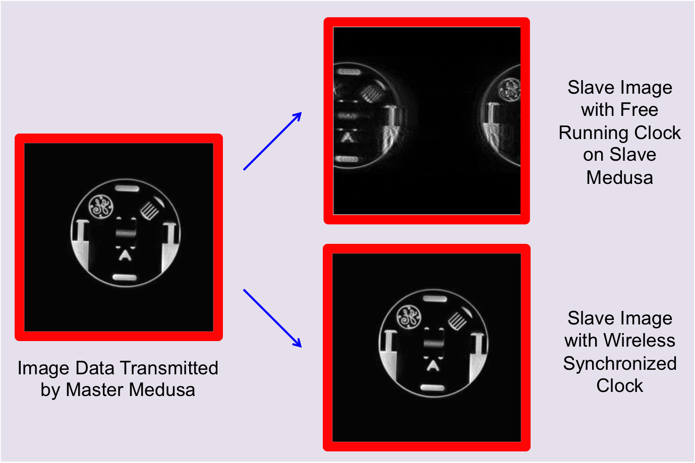
With the transmit power of the antenna set to be 20dBm, we were able to send the clock wirelessly between the two antennas to a distance of 21 cm. The clock signal at the receive end was measured using an oscilloscope (Figure 4). We sent an image of a GE phantom across the data line. In addition, the trigger signal was sent across a separate line. When comparing the looped back image as seen by the master medusa and the image sent from the master Medusa to the slave Medusa, there were minimal artifacts of the type that would appear if the clocks were free running (Figure 5).
Additional changes in the antenna may be explored. For instance, the monopoles may be replaced with dipole antennas that would improve compactness. The addition of a parabolic shield may also be used to reduce unwanted property coverage and enhance signals in desired regions. The next steps would be to explore methods to make the data and trigger lines wireless. The data line may potentially be replaced with an off-the-shelf WiFi module (ie Wiced Feather, Photon). The trigger lines may ideally be replaced with off-the-shelf wireless digital signal links (such as Linx modules).
Acknowledgements
The authors thank GE Healthcare Research Support, NIH Grant R01EB008108, P01CA15999, R01EB019241, the Stanford Graduate Fellowship and National Science Foundation for funding sources.References
[1] Bosshard J, Wright S, Phase Correction with Asynchronous Digitizers, ISMRM 23, 2015 #1787
[2] Stang P, Conolly S, Santos J, Pauly J, Scott G, Medusa: A Scalable MR Console Using USB, IEEE Transactions on Medical Imaging, 2012
Figures