2691
Low IF Passive Mixer Topologies for Low Power MRI Front Ends1Institute for Biomedical Engineering, University and ETH Zurich, Zurich, Switzerland, 2Electrical Engineering, Stanford University, Stanford, CA, United States, 3GE Healthcare, Aurora, OH, United States
Synopsis
As MRI array counts expand, there is growing interest in moving more of the receive electronics onto the array, the ultimate goal being wearable, and cordless arrays. This places severe constraints on the maximum feasible power consumption per channel. We explore low power front-end topologies employing passive mixers. If combined with low-power high resolution successive approximation ADCs or continuous time sigma delta ADCs, receive arrays at only 100mW per channel may be feasible.
Introduction
In the modern era of MRI, high channel count arrays enable accelerated imaging, yielding shorter scan times, and better image quality. However, receive arrays are often bulky, requiring extensive cabling and complex layout of RF cable traps to prevent undesired RF interactions. The desire for lightweight, flexible receive arrays is driving the development of more electronics at the coil, with the ultimate goal being wireless arrays. A large coil array must also combine analog signal processing blocks (preamps, down-conversion mixers, filters and analog-to-digital converters), but the distribution of these components is an open question. Recent wireless standards (802.11ac,ad) are now capable of the data rates needed for MRI, but a major issue is how to design a low-power high dynamic range receive chain. High resolution successive approximation (SAR) and continuous-time sigma-delta ADCs can achieve 10mW but require RF signal down-conversion to a low intermediate frequency (IF) below 1-2 MHz. Here, we present a test platform to assess low-IF and sliding-IF front-ends using low-power, passive mixers for MRI target applications.Methods
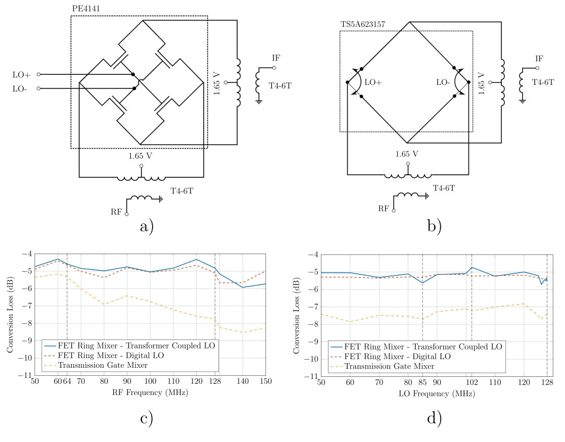
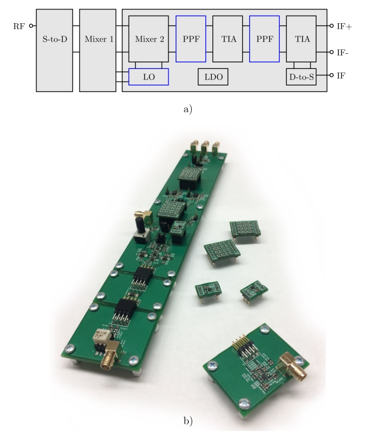
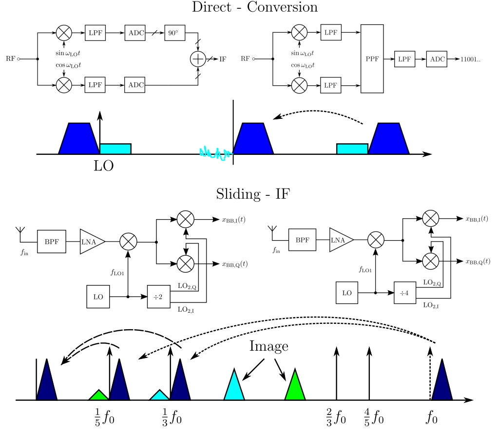
First, we prototyped logic-switched passive mixers using fast (300 MHz BW) SPDT analog switches (TS5A623157) and the PE4141 FET ring mixer, cf. Figure 1a,b. The FET ring was found to be superior in conversion loss and bandwidth and was used for subsequent development, cf. Figure 1c,d. A mixer front-end test platform was then designed, enabling extensive testing for MR relevant test scenarios. The modular design, cf. Figure 2, allowed for testing of two low-IF receiver architectures1: sliding-IF and direct-conversion, cf. Figure 3. A MEMS oscillator (SiT8008B) was used, and quadrature LO signals generated through divide-by-4 or divide-by-2 circuits using D-type flip-flops2 (NXP 74AUP1G74 ). A 25% or 50% quadrature duty cycle was selectable. Image rejection employed 2-4 polyphase filter banks, for which design equations enable accurate bandwidth and filter pole frequency selection3. Polyphase filters (PPF) can be inserted before or after transimpedance amplifier (TIA) blocks to enable voltage- and current-mode testing, the latter being reported to be promising in terms of performance enhancements4. TIAs - fully differential amplifier based - were used to replace transformer coupling of signals for MRI compatibility.Results
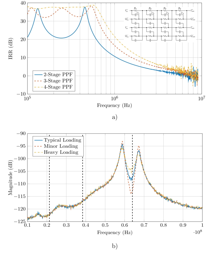
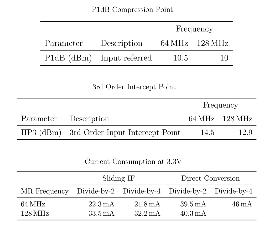
A 3-stage PPF provided a good trade-off between sufficient image rejection with additional headroom for unexpected degeneration by quadrature signal inaccuracy, PPF parts precision and PPF attenuation, cf. Figure 4a. Measurements showed that a divide-by-4 and 25% duty cycle LO generation was superior in terms of image rejection. Minor effects on image rejection were seen, depending on the receiver architecture, whether sliding-IF or direct-conversion. However, the sliding-IF architecture showed significantly better performance in terms of power consumption - more than 50% lower compared to the direct-conversion low-IF scheme. The sliding-IF architecture suffers from frequency images in both the first and second mixer stage. The second image is eliminated by quadrature down-conversion and image rejection through polyphase filtering. The first image, in an MRI scenario, will fold noise on top of the desired band upon down-conversion, in theory degrading the system noise figure by as much as 3dB. However, measurements showed that the characteristics of the noise floor of a MR coil/preamp combination alleviate this restriction, cf. Figure 4b. A noise figure degradation of less than 0.5dB could be estimated and should be easily improved by an image reject filter inserted between the first and second mixer stage to enhance noise performance. The mixer front-end, with sliding-IF architecture and divide-by-4 25% duty cycle LO generation, achieved an image rejection based on 3-stage polyphase filtering of more than 30dB, while showing an IIP3 of 14.5 dBm at a power consumption of 71.9 mW for a typical 64 MHz MRI scenario, cf. Figure 5.Discussion
A key enabler of low-power MRI receive arrays are new successive approximation (SAR) ADCs such as the LTC2380-24 (24 bits, 2 MSa/s, SNR of 98.5dB at 0.1MHz, 4ps jitter, 28 mW power). The MAX11905 offers 20 bits, 1.6 MSa/s, a SNR of 98dB, for only 9mW. Both require a low-IF receiver because of the lower sampling rates, and jitter. The Sliding-IF has a unique property that no RF converted signals or clocks are near the MRI frequency. This means the first mixer and clock could be distributed with the coil preamp, and the lower frequency mixers and ADCs located in side-pods. RF cable traps (which heat) could be replaced by differential IF/clock pass-band filters (which don’t heat). If low-power SiGe preamplifiers could be designed for 15-20mW, a low-power ADC and the low-power mixer front-end proposed here may enable a receiver front-end with a total power consumption as low as 100mW per channel.Acknowledgements
We would like to thank GE Healthcare for their research support. NIH Grant support: R01EB019241.References
1. B. Razavi, RF Microelectronics, ser. Prentice Hall Communications Engineering and Emerging Technologies. Prentice Hall, 2012.
2. A. Mirzaei, H. Darabi, J. C. Leete, and Y. Chang, “Analysis and optimization of direct-conversion receivers with 25% duty-cycle current-driven passive mixers,” IEEE Transactions on Circuits and Systems I: Regular Papers, vol. 57, no. 9, pp. 2353–2366, Sept 2010.
3. K. Schmidt, “Phase-Shift Network Analysis and Optimization,” QEX, 1998.
4. A. Liscidini, “Fundamentals of modern RF wireless receivers: A short tutorial,” IEEE Solid-State Circuits Magazine, vol. 7, no. 2, pp. 39–48, Spring 2015.
Figures