2687
A Convertible Magnet Array and Solenoid Coil for a Portable Magnetic Resonance Imaging (MRI) System1EPD, Singapore University of Technology and Design, Singapore, Singapore, 2Department of Surgery, National University of Singapore, Singapore, Singapore
Synopsis
A magnetic resonance imaging (MRI) for outdoor in-situ scanning is promising for biological studies. Here we propose a portable MRI system in which both the magnet array and the transceiver coil can be physically opened and closed. This is for imaging long objects in situ where cutting the object and fitting it into a bore for scanning is not an option. A convertible magnet array is designed where the force to open and to close the magnet array is minimized based on an analytical solution. Meanwhile, a convertible solenoid coil is proposed as an RF transceiver coil.
Introduction
Portable device for magnetic resonance imaging (MRI) has captured more and more attention recently. Besides challenges such as low signal-to-noise ratio (SNR), it is still a challenge to image long objects in-situ, for example, the stems of plants or branches of trees when cutting them to fit in the bore of an MRI scanner is not an option. One existing solution is to use an open C-shaped MRI on a trolley to gain access to the object under measurement (shown in Fig. 1).1 However, the system is complex and heavy, and it is sensitive to vibration when it is transported. In the meanwhile, the radiofrequency (RF) transceiver needs to be winded around the imaged objects on site, which is time-consuming and cannot ensure the performance of the coil. We propose a system with improved robustness and convenience with both the magnet array and solenoid coils convertible.Methods
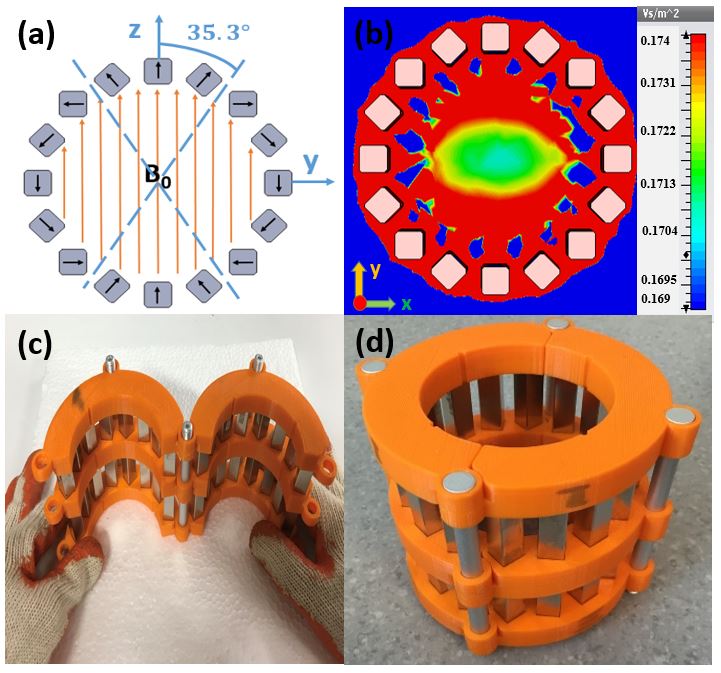
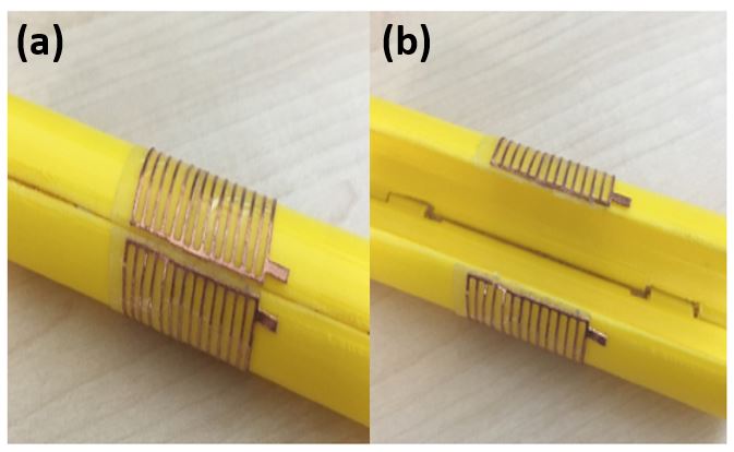
Magnet Array Design: The Main magnetic field (B0 field) is provided by a Halbach cylinder with a diameter of 88 mm. It consists of 16 rungs, and each rung is an N52 NdFeB magnet bar with a dimension of cm. The cross section view of the Halbach cylinder and the distribution of the magnetic field are shown in Fig. 2. The main objective in the design of the convertible array is to minimize the force to open and to close the magnet array while maintaining the field strength and distribution for imaging. Considering two magnetic dipoles with magnetic moment and respectively, the magnitude of the force along a line connecting the two magnetic dipoles is given by: $$$F(\theta)=\frac{3\mu_0{m_1m_2}}{4\pi{r^4}}(3cos^2(\theta)-1)$$$, where $$$\mu_0$$$ denotes the permeability of free space, $$$\theta$$$ and $$$r$$$ are the angle and distance between the two dipole moments, respectively.2 Based on the equation aforementioned, the force $$$F(\theta)$$$ shows an angular dependence. When $$$\theta_m=54.73^\circ$$$, $$$F(\theta_m)$$$ is minimum. According to the magnetization pattern of a Halbach cylinder, at the angle $$$\alpha=35.27^\circ$$$, Halbach array can be spilt into two parts without attractive or repulsive forces along the joining line (shown in Fig.2(a)). The simulated magnetic field has a field homogeneity of 3249 ppm and an average field strength of 171 mT over the volume of interest (VOI) which is a spherical one with a diameter of 10 mm (shown in Fig. 2(b)). The magnet array with harness was fabricated and is shown in Fig. 2(c-d). RF Coil Design: A normal solenoid coil is continuous and cannot be opened, which cannot be used in the proposed system. A convertible solenoid RF coil is proposed to work with the convertible magnet array as transceiver. It is shown in Fig. 3(a). Since copper wires are pliable, they enable the convertibility of the proposed solenoid without degrading the performance. The currents flowing on the input path and the output path have the same magnitude yet opposite directions, thus the field generated by them will vanish in the far field. The convertible solenoid was fabricated. It is shown in Fig. 4.Results
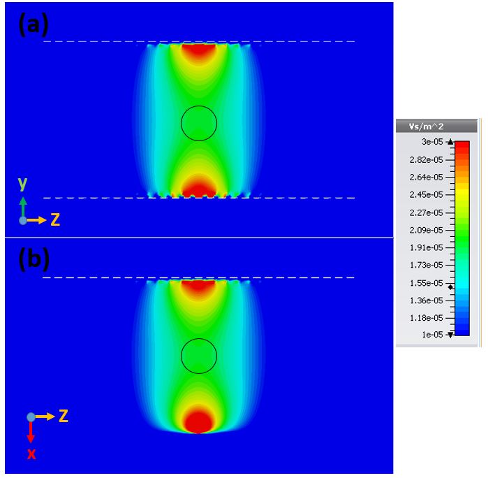
The magnetic field of the fabricated magnet array is measured by a 3-channel Hall effect Gaussmeter (Model 460, Lake Shore Cryotronics, Inc., Westerville, OH). The probe is installed on an automated measurement bench based on 3-axis motion platform. The measured field strength inside the VOI ranges from 161.8 ~ 162.4 mT at $$$25^\circ$$$. Fig. 3 (b) shows the distribution of the simulated magnetic field of the proposed coil.3 It has a similar field distribution in the central volume as that of a normal solenoid coil.4 Fig. 5 (a) and (b) shows the y-components of the B1-field of the proposed solenoid coil on the yz- and the xz-planes, respectively.Discussion
The measured field strength agrees with simulated one while it is slightly lower. It may be due to the fabrication imperfection that the remanent magnetization does not satisfy the N52 grade. The measured field homogeneity (3700 ppm) agrees well with the simulation. It is good for imaging. As shown in Fig. 5, the y-components of the B1 field of the convertible solenoid coil has good consistency in field homogeneity on orthogonal planes (yz- and xz-planes). It is good for RF excitation and signal detection.Conclusion
The design of a convertible magnet array and solenoid coil for a portable MRI scanner is presented. The force to open and close the magnet array is minimized based on an analytical solution. A convertible solenoid RF coil is proposed. It has a similar magnetic field distribution as that of a normal solenoid coil. Proper gradient coils will be designed and added to the system for imaging later.Acknowledgements
This research was supported by SUTD President's Graduate Fellowship. I would like to take this opportunity to express my sincere gratitude for their support.References
1. Kimura, T., Geya, Y., Terada, Y., et al. Development of a mobile magnetic resonance imaging system for outdoor tree measurements. Review of scientific instruments, 82(5), p.053704.
2. Windt, C. W., Soltner, H., Van Dusschoten, D., et al. A portable Halbach magnet that can be opened and closed without force: The NMR-CUFF. Journal of Magnetic Resonance, 208(1), 27-33.
3. CST, Computer Simulation Technology AG, Darmstadt, Germany.
4. Bolz, R.E., CRC handbook of tables for applied engineering science. CRC press, 1973.
Figures