2686
Minimum Current Ripple in the Gradient Array System by Applying Optimum-Phase Pulse-Width Modulation Pattern1National Magnetic Resonance Research Center (UMRAM), Bilkent University, Ankara, Turkey
Synopsis
Phase-shifted Pulse Width Modulation (PWM) technique is implementable in stacked and parallel configuration of the H-bridge gradient amplifiers. However, in the gradient array systems where one stage amplifier is sufficient to drive each element, phase-shifted PWM is not feasible. In this work, similar technique is implemented by utilization of the coupling between the elements of the array and finding the optimized phases for each channel in order to have minimum current ripples. This method is tested for different gradient fields and high ripple reduction percentages achieved both in simulations and experiments.
Introduction and Purpose
Phase-shifted Pulse-Width Modulation (PWM) method has been used in stacked or parallel configuration of switching H-bridge amplifiers in order to reduce the output current ripples and to increase their effective frequency in the gradient coils1. This leads to smaller ripple-cancellation and LC filters at the output stage of the x, y and z gradient amplifiers2. On the other hand, multiple gradient coils have been proven to generate linear gradient fields as well as higher order spherical harmonics for both encoding and shimming purposes3,4. Since multiple coils are driven with independent amplifiers, required voltage for each gradient coil may be reduced which makes only one stage H-bridge feasible. Normally, one stage H-bridge amplifiers do not have phase shifted PWM capability. In our study, gradient coil elements are mutually coupled that should be compensated during rising and falling edges of the current. We demonstrate that mutual coupling between the elements can be utilized to reduce output ripple in one stage H-bridge amplifiers by applying optimum-phase PWM pattern for each channel separately.Methods
In a gradient amplifier, current ripples occur as a result of pulsed voltages with a determined duty-cycle applied to an inductive load. In this work, center-aligned PWM is used which has better harmonic contents and results in increased effective frequency. The PWM phases for each channel are optimized in order to get the minimum overall current ripple energy for the channels (Eq. 1). This is done by using built in “Global Search” optimization in MATLAB (R2016b-Mathworks Inc.) which optimizes function with respect to $$$\Delta t$$$ for each channel where is the current ripple of $$$k$$$th channel with no DC content that are elements of vector in Eq. 2. In this equation is diagonal matrix containing resistance of each channel and is inductance matrix containing self-inductance of each channel along with the mutual coupling between them.
$$\underset{\Delta t}{\text{min}}\sum_{k=1}^N\int\limits_{pwm\ period}i_k^2(t-\Delta t_k)dt$$
$$\boldsymbol{V}_{N\times1}(t)=\boldsymbol{R}_{N\times N}\cdot\boldsymbol{I}_{N\times1}(t)+\boldsymbol{M}_{N\times N}\cdot \frac{d}{dt}\boldsymbol{I}_{N\times1}(t)$$
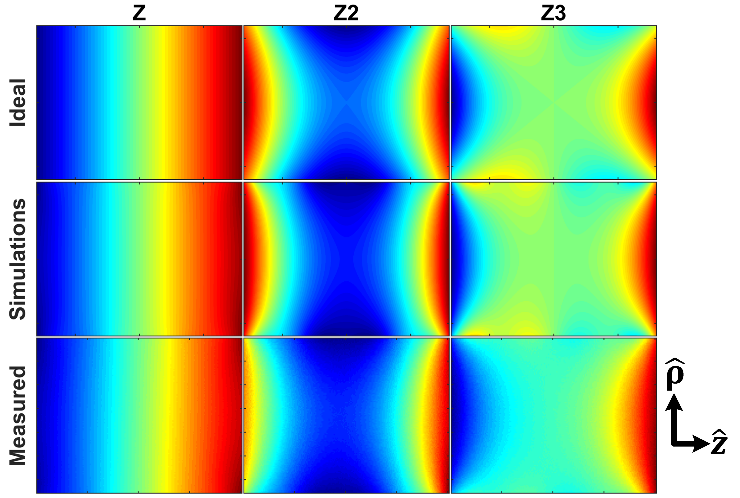
Since there are many parameters specific for different gradient array systems, we have evaluated this method in our 9 channel z-gradient array prototype with a 27.5 cm length and 25 cm radius. Each channel has 36 turn windings in $$$\hat{ \phi}$$$ direction and placed directly next to the neighboring channel. The current combinations producing linear z-gradient field and two nonlinear second ($$$z^2$$$) and third order ($$$z^3$$$) fields (Fig.1) have been considered to simulate the current ripple reduction which is experimentally verified for linear z-gradient. Nine home-built, H-bridge amplifiers with 20 Amps and 40 Volts VI capabilities which are controlled independently by an FPGA (Xilinx/Virtex-5) with $$$50\mu s$$$ PWM period and developed user interface to achieve desired flexibility in terms of control signals.
Results
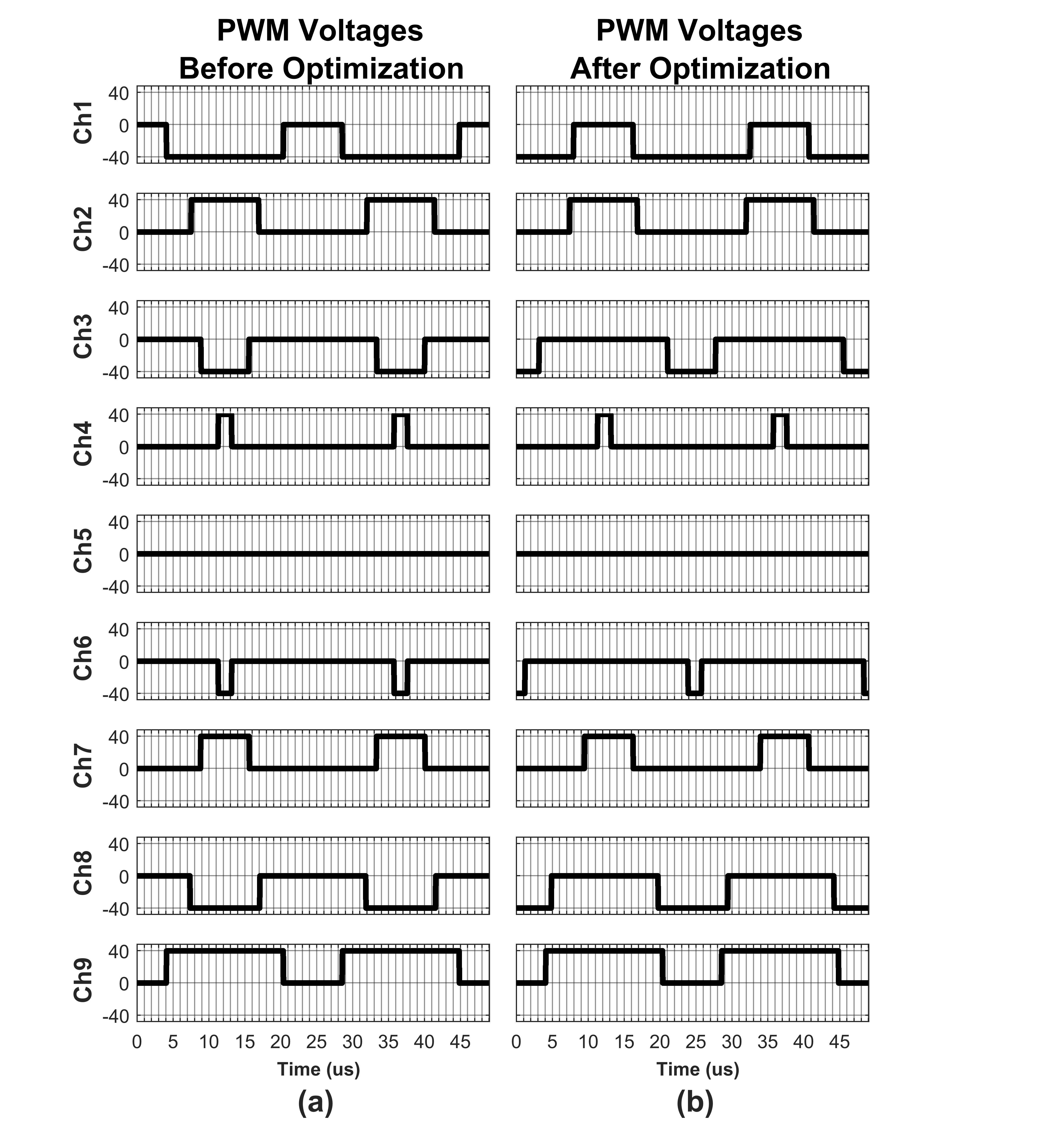
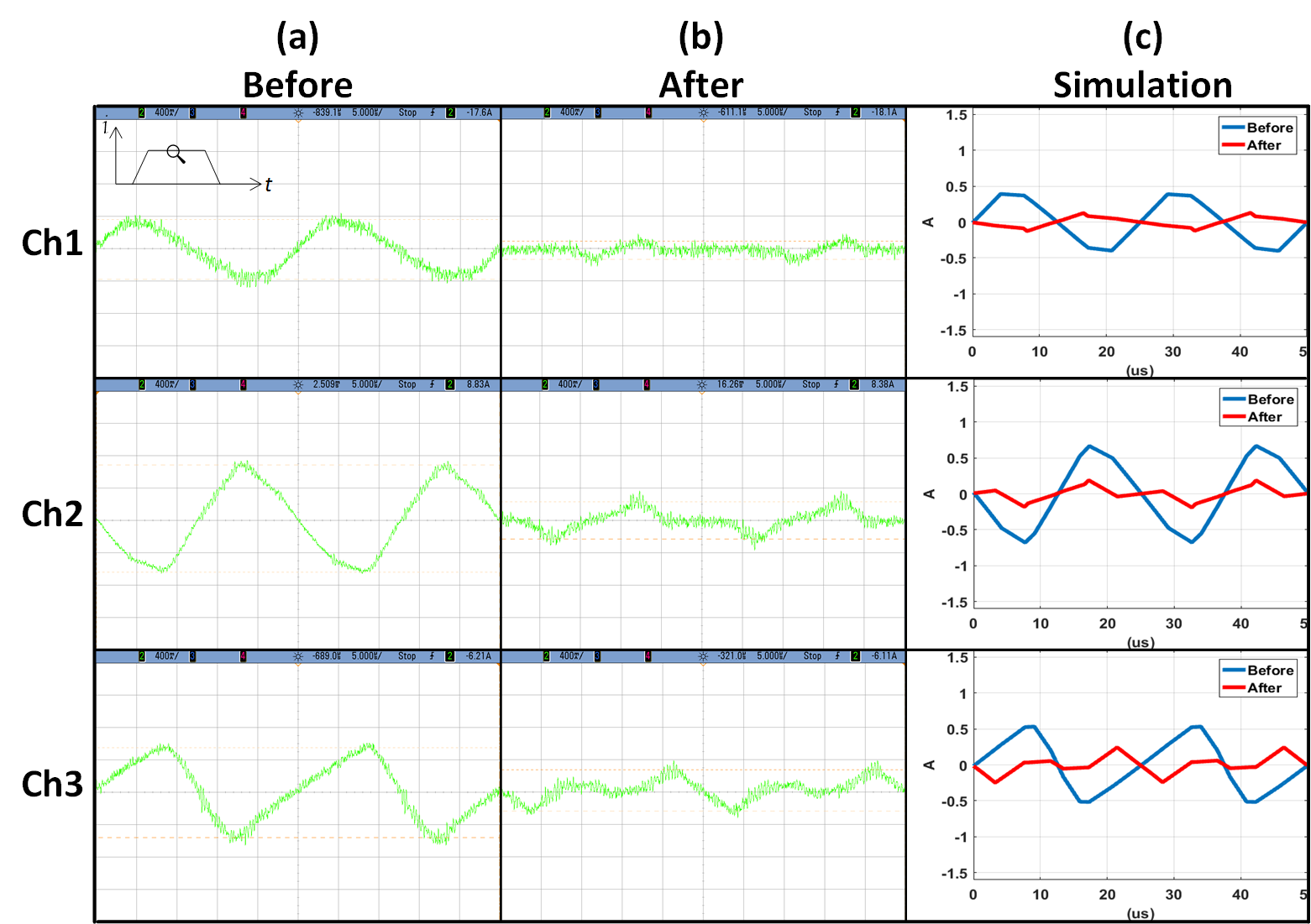
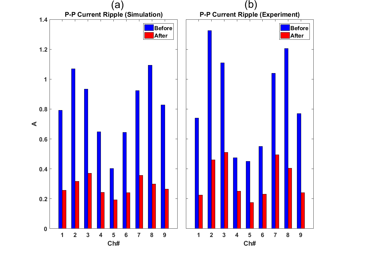
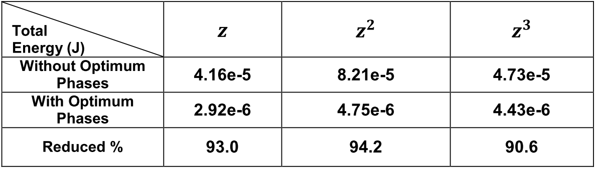
PWM pulses before and after phase optimization required for each channel to create the linear z-gradient are given in Figure 2. In Figure 3, there are zoomed-in flat top waveforms containing current ripples for 3 channels as an example out of 9 channel generating linear z-gradient before and after optimization in experiment (Fig.3a (Before), b (After)) and simulation (Fig. 3c). Peak-to-peak current ripple values in 9 channels for linear field are given in Figure 4 before and after optimization in simulation (Fig. 4a) and experiment (Fig. 4b). Figure 5 shows total current ripple energy with and without optimum phases and associated reduction percentage for linear and both nonlinear cases.Discussion and Conclusion
When the current ripples of the coupled channels are in phase (i.e. same direction) due to the Lenz’s law they will reduce each other and for the other case when the ripples are not in phase (i.e. reverse direction) optimum phases are calculated to reduce the current ripple. These phase shifts are applied within a period and do not affect the phase of the whole signal. Relative reduction of the peak-to-peak current ripples and also shape of their waveforms are very similar between the simulations and experiments. This reduction is not evenly distributed between the channels, but most of the channels with less reduction percentage have already small ripple peaks compared to the others. In this work a 9-channel solenoid was used, however it can be extended to any array systems with known mutual coupling between the coils. Although this method doesn’t eliminate the need for the ripple cancelation filters but it paves the way to simpler and smaller filter design in gradient array systems and opens new horizons in possible advantages of inductive coupling.Acknowledgements
No acknowledgement found.References
1. Robinson, F. V. P. "The interleaved operation of power amplifiers." Power Electronics and Variable Speed Drives, 1998. Seventh International Conference on (Conf. Publ. No. 456). IET, 1998.
2. Sabate, Juan, et al. "Ripple cancellation filter for magnetic resonance imaging gradient amplifiers." Applied Power Electronics Conference and Exposition, 2004. APEC'04. Nineteenth Annual IEEE. Vol. 2. IEEE, 2004.
3. Jia F, Schultz G, Testud F, Welz AM, Weber H, Littin S, Yu H, Hennig J, Zaitsev M. Performance evaluation of matrix gradient coils. MAGMA 2016;29:59–73.
4. Juchem C, Rudrapatna SU, Terence W. Nixon TW, de Graaf RA. Dynamic multi-coil technique (DYNAMITE) shimming for echo-planar imaging of the human brain at 7 Tesla. Neuroimage 2015;105:462–447.
5. K. Ertan, S.Taraghinia, A. Sadeghi, E. Atalar “A z-gradient array for spatially oscillating magnetic fields in multi-slice excitation” Magn Reson Mater Phy (2016) 29: 1. doi:10.1007/s10334-016-0568-x, Abstract No:81
Figures