2681
An insert gradient for zero-echo-time imaging with 200 mT/m at full duty cycle1Institute for Biomedical Engineering, University and ETH Zurich, Zurich, Switzerland, 2Philips GmbH Innovative Technologies, Hamburg, Germany, 3Philips AG, Zurich, Switzerland, 4Futura Composites BV, Heerhugowaard, Netherlands
Synopsis
Zero-echo-time (ZTE) techniques enable imaging of tissues with very short T2s, e.g. bone or myelin. Their performance directly scales with gradient strength G, which depends on the target T2 and spatial resolution. With present-day gradients the spatial resolution for T2s on the order of 100 μs is limited to several millimetres. To improve the resolution, considerably higher gradient strengths are required. As a further challenge of ZTE sequences, the strong gradients are applied with full duty cycle. The goal of this work was to develop a gradient coil that meets these challenges, offering very high amplitude at full duty cycle.
Purpose
To develop a gradient coil capable of performing zero-echo-time (ZTE) MRI with continuous gradient amplitude of 200 mT/m in humans for targeting tissues with T2s below 100 μs at high resolutionIntroduction
Zero-echo-time and related techniques enable efficient imaging of tissues with very short T2s, e.g. bone, tendons, or myelin1-7. Their performance directly scales with gradient strength G, which depends on the target T2 and spatial resolution $$$\Delta r$$$ according to $$$G=\pi/(\gamma \cdot\Delta r\cdot T2)$$$7. Therefore, with present-day gradients of conventional human MRI scanners the spatial resolution for T2s on the order of 100 μs is limited to several millimetres. To improve the resolution, considerably higher gradient strengths are required.
As a further challenge of ZTE sequences, the strong gradients are applied with full duty cycle as the gradients are operated quasi-continuously with rotating 3D radial directions. As a benefit, gradient switching is reduced to minor changes in angular direction, thus leading to strongly reduced eddy currents and acoustic noise.
The goal of this work is to develop a gradient coil that meets these challenges, offering very high amplitude at full duty cycle.
Methods
Specifications: The following requirements were defined for the design of the gradient coil.
- A target T2 of 60 μs to be imaged at a resolution of 1 mm, thus requiring at least G = 196 mT/m to be generated with 100 % duty cycle using rotating gradients.
- Target anatomies: brain, MSK
- FOV: ellipsoidal AP x RL x FH = 220 x 220 x 200 mm3
- Linearity in FOV: maximum local deviation from nominal gradient strength 20%
- Unambiguity: no signal aliasing into FOV up to a Z distance of 250 mm from iso-centre
- Active shielding
- Power supply: max. current 720 A, max. voltage 650 V
- Cooling: max. heat extraction 24 kW
- Maximum outer diameter 680 mm, minimum inner diameter 330 mm
- Easy exchange at field
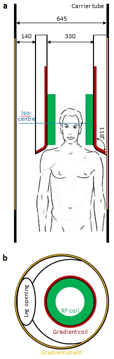
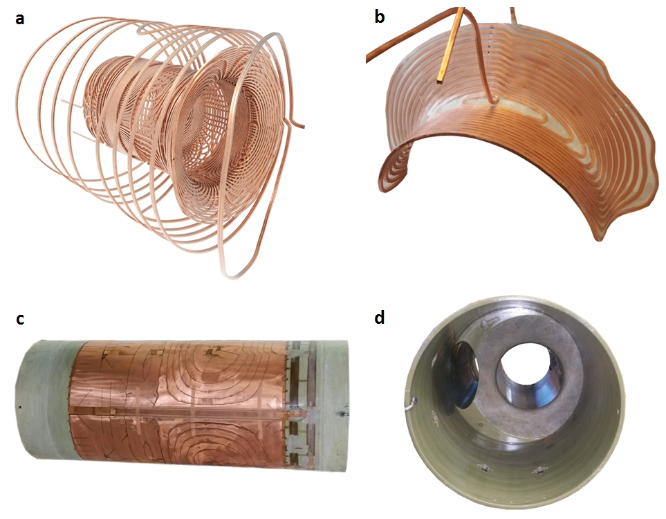
Design: The above specifications were realised with the following design (Figs. 1 and 2).
- Cylindrical bore, asymmetric in Z with conical widening at patient side
- Asymmetric left-right with iso-centre shifted horizontally by 65 mm to make space for the other leg in lower extremity imaging
- Outer carrier tube of length 1700 mm
- Single-layer coils with hollow conductors for direct cooling on all axes
- Force balancing
MRI: Phantom images were acquired with the ZTE technique using a 1H-free surface coil with diameter 70 mm8 and data acquisition via a custom-made spectrometer9. Volunteer scanning was performed with ethics approval using gradient echo and ZTE sequences and a custom-made quadrature RF birdcage in transmit-receive operation. All experiments were performed using a 3T Achieva MRI system (Philips Healthcare, Best, The Netherlands) equipped with a dual-mode gradient amplifier (Copley 787, Copley Controls, Canton, MA, USA) and a standard heat exchanger (Neslab II, Thermo Electron Corp, Newington, NH, USA).
Results
The gradient coil built achieves G = 200 mT/m with slew rate S = 600 mT/m/ms or G = 100 mT/m with S = 1200 mT/m/ms in parallel or serial mode, respectively, of the gradient amplifier employed. It enables full-duty cycle ZTE scanning at maximum gradient strength.
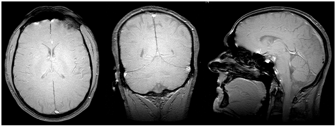
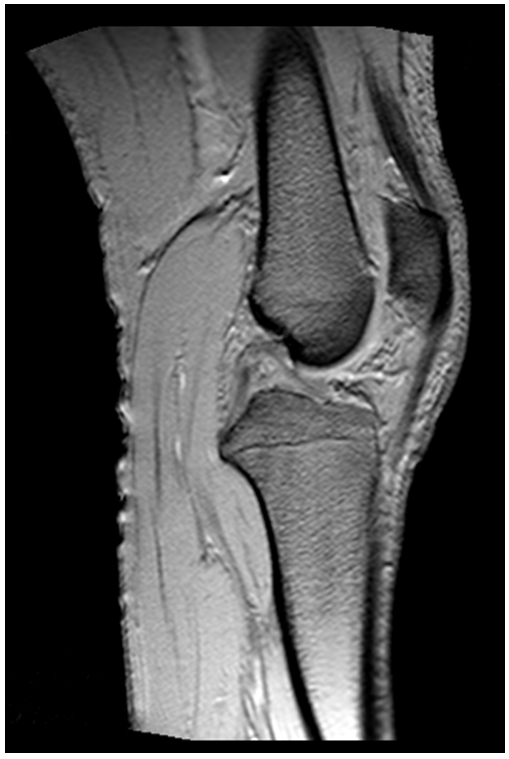
The coil allows for head and MSK imaging with only minor distortions in the FOV which can be corrected using standard non-linearity correction10 (Figs. 3 and 4). At all levels of performance no considerable PNS was experienced so far. For acoustic noise of conventional sequences, maximum SPL values of 95 – 105 dB were observed, which were reduced to comfortable levels with appropriate hearing protection. SPL in ZTE scanning was 75 dB.
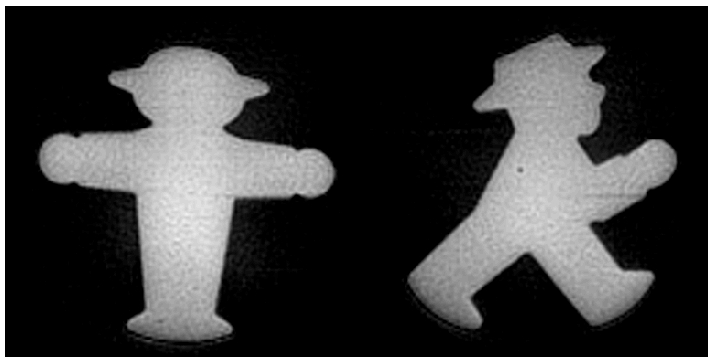
As a ZTE example, Figure 5 shows images with 0.5 mm in-plane resolution of
rubber samples with T2* ≈ 400 µs
acquired with G = 92 mT/m in continuous operation.
Discussion
In this work, a gradient coil was presented dedicated to the requirements of short-T2 MRI, in particular ZTE imaging. Similar to previous attempts to high-performance gradients11-14 it was designed and built as an insert coil for a standard amplifier and cooling. However, higher amplitudes and slew rates were achieved with the present gradient, partly due to a smaller bore diameter. Furthermore, these specifications are available at full duty cycle. Only for the large-bore Connectome gradient15 a higher strength has been reported so far, requiring however a dedicated environment and providing considerably lower slew rates. In summary the presented gradient system has a high potential for high-resolution in vivo imaging of T2s on the order of 100 μs and below. Furthermore, it is also promising for neuro applications using rapid scanning with EPI or spiral imaging as well as strong diffusion weighting.Acknowledgements
No acknowledgement found.References
1. Hafner S. Fast imaging in liquids and solids with the back-projection low-angle shot (BLAST) technique. Magn Reson Imag 1994;12:1047-1051.
2. Madio DP, Lowe IJ. Ultra-fast imaging using low flip angles and FIDs. Magn Reson Med 1995;34:525-529.
3. Kuethe DO, Caprihan A, Fukushima E, Waggoner RA. Imaging lungs using inert fluorinated gases. Magn Reson Med 1998;39:85-88.
4. Idiyatullin D, Corum C, Park JY, Garwood M. Fast and quiet MRI using a swept radiofrequency. J Magn Reson 2006;181:342-349.
5. Wu YT, Dai GP, Ackerman JL, Hrovat MI, Glimcher MJ, Snyder BD, Nazarian A, Chesler DA. Water- and fat-suppressed proton projection MRI (WASPI) of rat femur bone. Magn Reson Med 2007;57:554-567.
6. Grodzki DM, Jakob PM, Heismann B. Ultrashort echo time imaging using pointwise encoding time reduction with radial acquisition (PETRA). Magn Reson Med 2012;67:510-518.
7. Weiger M, Pruessmann KP. MRI with zero echo time. eMagRes. Volume 1. Chichester, United Kingdom: John Wiley & Sons, Ltd; 2012. p 311-322.
8. Rösler MB, Weiger M, T. S, Brunner DO, R. F, Pruessmann KP. Ultrasonic soldering on glass for the construction of MRI coils with minimized background signal in short-T2 images. In Proceedings of the 33rd Annual Scientific Meeting of ESMRMB, Vienna, Austria, 2016. p.87.
9. Weiger M, Brunner DO, Dietrich BE, Muller CF, Pruessmann KP. ZTE imaging in humans. Magn Reson Med 2013;70:328-332.
10. Doran SJ, Charles-Edwards L, Reinsberg SA, Leach MO. A complete distortion correction for MR images: I. Gradient warp correction. Physics in medicine and biology 2005;50:1343-1361.
11. Kimmlingen R, Eberlein E, Gebhardt M, Hartinger B, Ladebeck R, Lazar R, Reese TG, Riegler J, Schmitt F, Sorensen AG, Wedeen V, Wald LL. An easy to exchange high performance head gradient insert for a 3T whole body MRI system: First results. In Proceedings of the 12th Annual Meeting of ISMRM, Kyoto, Japan, 2004. p.1630.
12. Wade TP, Alejski A, Bartha J, Tsarapkina D, Hinks RS, McKinnon GC, Rutt BK, McKenzie CA. Design, construction and initial evaluation of a folded insertable head gradient coil. In Proceedings of the 22nd Annual Meeting of ISMRM, Milan, Italy, 2014. p.4851.
13. Lee S-K, Mathieu J-B, Graziani D, Piel J, Budesheim E, Fiveland E, Hardy CJ, Tan ET, Amm B, Foo TKF, Bernstein MA, Huston J, Shu Y, Schenck JF. Peripheral nerve stimulation characteristics of an asymmetric head-only gradient coil compatible with a high-channel-count receiver array. Magn Reson Med 2015:n/a-n/a.
14. Mathieu JB, Lee SK, Graziani D, Lin J, Budesheim E, Piel JE, Thiagarajan N, Hardy CJ, Schenck JF, Tan ET, Fiveland E, Park K, Hua Y, Bernstein MA, Huston J, Shu Y, Foo TKF. Development of a dedicated asymmetric head-only gradient coil for high-performance brain imaging with a high PNS threshold. In Proceedings of the 23rd Annual Meeting of ISMRM, Toronto, Canada, 2015. p.1019.
15. McNab JA, Edlow BL, Witzel T, Huang SY, Bhat H, Heberlein K, Feiweier T, Liu K, Keil B, Cohen-Adad J. The Human Connectome Project and beyond: initial applications of 300mT/m gradients. NeuroImage 2013;80:234-245.
Figures