2680
Dual-layered multi-channel B0 and RF coil setup for an improved shimming performance at 9.4 Tesla1High-Field Magnetic Resonance Center, Max Planck Institute for Biological Cybernetics, Tübingen, Germany, 2Institute of Neuroscience and Psychology, University of Glasgow, Glasgow, United Kingdom, 3Biomedical Magnetic Resonance, University Hospital Tübingen, Tübingen, Germany
Synopsis
Multiple local shim coils can be used to improve the B0 homogeneity at ultra-high field. In this work, a dual-layered multi-channel B0 and RF coil setup is presented that allows a flexible design of the shim coil without influencing the RF performance. It is shown that a 16 channel B0 coil in combination with a standard 2nd order spherical harmonics (SH) shim system can achieve a higher degree of B0 homogeneity than a 3rd order SH shim system in the case of whole-brain shimming.
PURPOSE
It has been shown recently in the literature that the pronounced B0 field inhomogeneities at ultra-high field (UHF) can be mitigated by the use of multiple local shim coils 1,2. The integration of these B0 coils into well-established multi-loop RF coils is challenging. In this work, we propose a coil arrangement that allows a flexible positioning of the B0 loops without compromising the RF transmit performance.METHODS
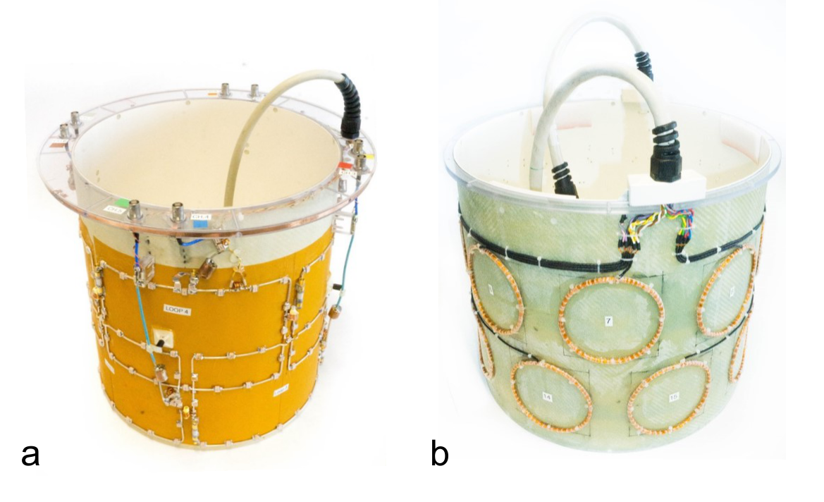
An 8-channel RF transceiver coil was constructed on a fiberglass cylinder having a diameter of 28cm (Figure 1a). The loops were arranged in two rows, which were rotated by 45° with respect to each other. Each loop had a height of 13cm and the overlap along the z-direction was 4.5cm. Decoupling between adjacent elements of the two rows was achieved by critical overlap. Adjacent loops within the same row were inductively decoupled. A slotted RF shield encompassed the transmit coil and permitted adding an array of B0 coils to the outer surface without influencing the transmit performance of the RF coil. This B0 coil array was mounted on an additional fiberglass cylinder (ø 36 cm) and comprised 16 circular loops, which had each 25 wire turns, a diameter of 10 cm, and were arranged in two rows (Figure 1b). A custom-built amplifier was used to drive the 16 coils individually. The maximal allowed amperage was set to 1.5 A per channel.
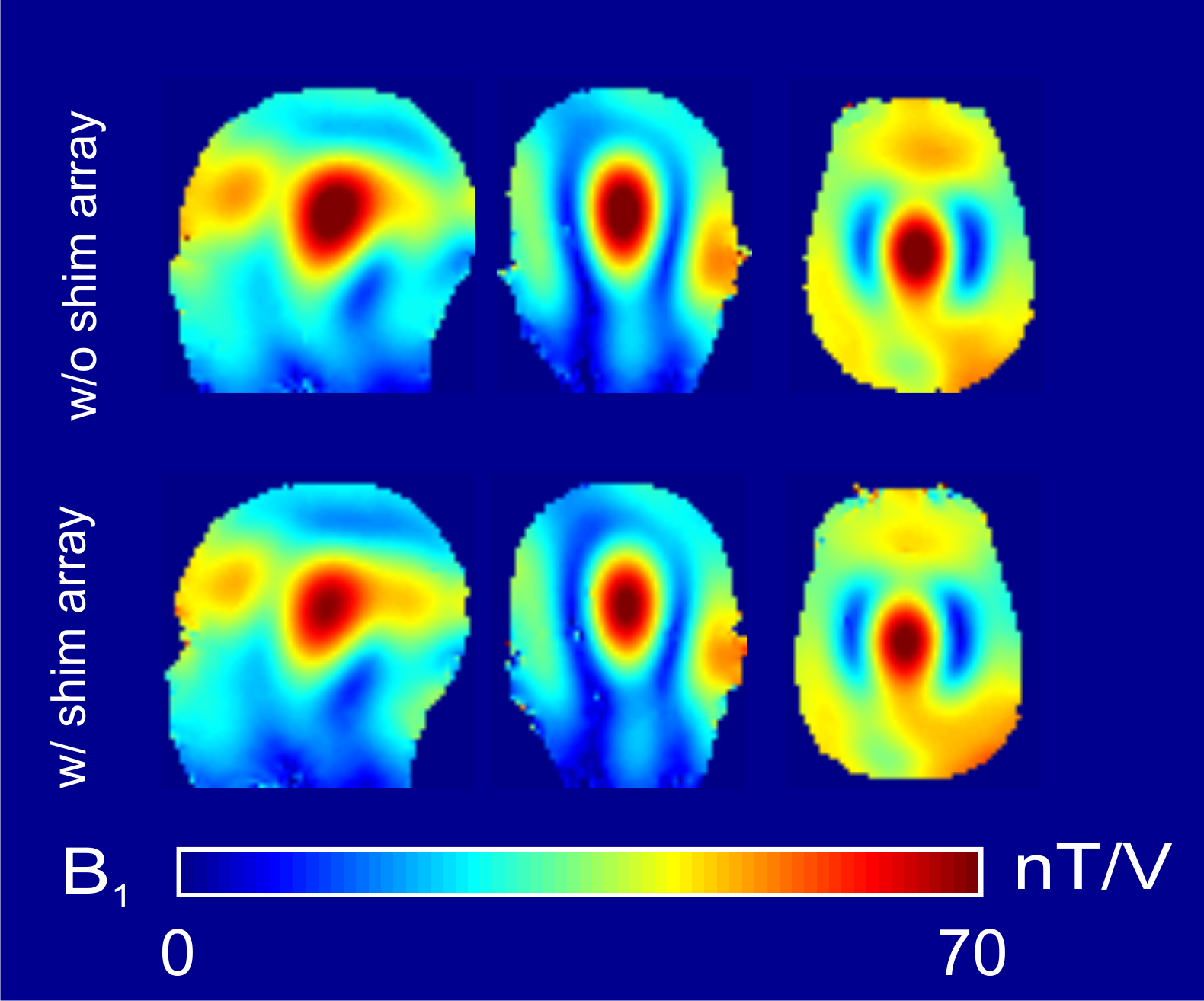
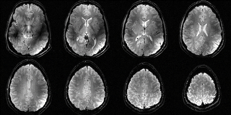
All the measurements were performed on a whole-body 9.4 T Siemens (Siemens Healthcare, Erlangen, Germany) MR scanner. The transmit performance of the RF coil was evaluated via electro-magnetic simulations and B1 mapping using actual flip angle mapping (AFI)3 in a head-shaped phantom. Gradient echo images (TE 12 ms, TR 155 ms, In-plane resolution 1x1 mm2, Slice thickness 1 mm, Acq. Time 30 s) were acquired in vivo to demonstrate the achievable image quality.
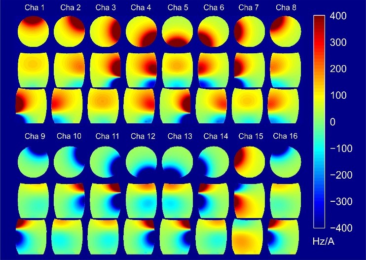
The fields produced by the 16 B0 coils were mapped with a 3D dual-echo gradient-echo sequence in a large cylindrical oil phantom. The imaging parameters were chosen as follows: TE1 1.1 ms, TE2 2.8 ms, TR 10 ms, Res 2 mm isotropic, FoV 384x312x288 mm3.
Simulations were performed to evaluate the performance of the proposed setup and to compare it to the in-built spherical harmonics (SH) shim system of the scanner in the case of global whole-brain shimming. To this end, B0 maps were acquired at 9.4 T without any prior shimming. Eight different shim scenarios were simulated: no shim, up to first/second/third order SH shimming, shimming using the 16 cha array with and without the three orders of the SH shim system.
RESULTS
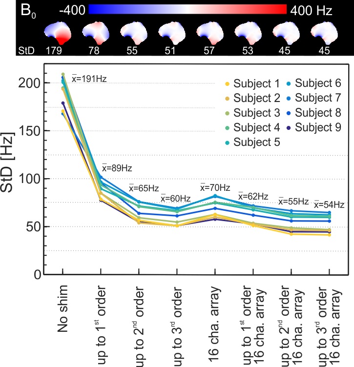
Figure 2 shows a B1 map acquired in the head-shaped phantom without the presence of the shim array. Adding the latter did not influence the observed B1 field distribution. The two rows of the RF coil provided a large longitudinal coverage, which is also demonstrated by the in vivo gradient echo images shown in Figure 3. The acquired B0 basis field maps are depicted in Figure 4. The comparison of the different shim scenarios is depicted in Figure 5. Using the proposed setup exclusively resulted in a mean standard deviation (StD) of 70 Hz across 9 subjects, which is comparable to the 2nd order SH shim (mean StD: 65 Hz). The 16-channel array in combination with the linear shims of the gradient system achieved on average the same degree of B0 homogeneity as the 3rd order SH shim (62 Hz vs. 60 Hz). If the second order shim is included, the setup (mean StD: 55 Hz) exceeds the performance of the 3rd order SH shim. The addition of the 3rd order SH shim did not provide any significant improvement.DISCUSSION
In this work, it could be shown that an array of 16 local B0 coils in combination with a standard in-built 2nd order SH shim system achieves in the case of global shimming a higher degree of B0 homogeneity as a third order SH shim system. Moreover, the shielding of the RF coil permits an easy modification of the B0 coil design without influencing the RF performance.CONCLUSION
Standard in-built SH shim systems normally have a large inductance, which prevents a rapid switching of the shim currents. This is however not an issue for the much smaller local B0 loops presented here. Hence, slice-wise dynamic shimming in conjunction with the linear shim channels is possible, which should further improve the achievable B0 homogeneity. Future work will focus on integrating a multi-channel receiver array into the transmit coil in order to improve the signal-to-noise ratio of the acquired MR images.Acknowledgements
We thank Nikolai Avdievitch for providing the equipment used to interface the coil with the scanner.References
1. Stockmann JP et al. A 32-Channel Combined RF and B0 Shim Array for 3T Brain Imaging. Magn Reson Med. 2016;75: 441–451.
2. Juchem C et al. Dynamic multi-coil shimming of the human brain at 7 T. JMR. 2011;212(2):280–288.
3. Yarnykh VL. Actual Flip-Angle Imaging in the Pulsed Steady State. Magn Reson Med. 2017;57:192–200.
4. Shajan
G et al. A 16-channel dual-row transmit array in combination with a 31-element
receive array for human brain imaging at 9.4 T. Magn Reson Med. 2014;71(2):870 – 879.
Figures