2679
Preliminary Metamaterial Design and Fabrication for MRI at 3TChao Luo1, Xiaoqing Hu1, Xiaoliang Zhang2,3, Xin Liu1, and Ye Li1
1Lauterbur Research Center for Biomedical Imaging, Shenzhen Institutes of Advanced Technology, Chinese Academy of Sciences, Shenzhen, People's Republic of China, 2Department of Radiology and Biomedical Imaging, University of California San Francisco, CA, USA, CA, United States, 3UCSF/UC Berkeley Joint Graduate Group in Bioengineering, San Francisco, CA, USA, CA, United States
Synopsis
In this paper, we designed and fabricated a kind of metamaterial with 9×9 cells, which bent on phantom and inserted to a birdcage volume coil to investigate the performance for 3T MRI. The results of simulations and phantom experiments agreed with each other very well indicate that the proposed metamaterial is able to increase the B1+ fields in some region closed to the surface of phantom. This improvement of B1+ fields will benefit to 3T MRI targeted clinical applications.
Introduction
Metamaterials with negative permeability provide unique capability of recovering the evanescent wave and have been proposed in magnetic resonance imaging (MRI) applications to image an object in deep sub-wavelength. The several kinds of microstructures of metamaterial were designed for MRI applications, such as Swiss roll cell [1], split resonance ring [2], the wire medium endoscope [3] and cylindrical rolled-up [4]. These metamaterials were difficult to use and complicated in design and fabrication. Furthermore, in order to improve the patient comfort, the metamaterial for MR imaging needs to be thin and flexible and fit different subjects. In this work, a compact and flexible metamaterial which is readily to be placed on the objects, was designed and fabricated for 3T MRI applications. The CST software (Darmstadt, Germany) was used to simulate and design the metamaterial. The phantom experiments were performed on 3T Siemens Tim Trio MRI to investigate the performance of the proposed metamaterial inserted to a volume coil.Methods and Materials
Simulation: The commercial CST software (Darmstadt, Germany) is used to design and simulate the metamaterial firstly. A planar metamaterial with a square winding microstructure was designed and fabricated for 3T MRI. In the design, the square spiral had 7 turns with line width 0.5mm, line space 0.1mm. Two square spirals were placed in parallel, which forms a double-sided square spiral. The resonance frequency of each double-sided square spiral is 123.2MHz. A quadrature 16-element high-pass birdcage coil with 312.5mm radius of end-ring and 350cm length was modeled as volume receive coil. A cylindrical phantom with 200mm in length and 57.5mm in radius was placed at the center of the birdcage volume coil as shown in Fig 1(a). The square spiral copper strips were etched on the two sides of a printed circuit board (Rogers 5880) using a standard PCB fabrication technology as shown in Fig 1(b). The metamaterial was inserted into the birdcage volume coil and bent on the cylindrical phantom as shown in Fig 1(c). The side length of the unit square cell was 15mm. The final fabricated metamaterial slab had 9×9 cells in a plane of total size 13.5×13.5cm2 as shown in Fig 1(b). Phantom studies: The metamaterial is bent on a cylindrical phantom from the MR manufacturer (filled with 1.24g/L NiSO4·6H2O and 2.62g/L NaCl, 57.5mm in radius and 200mm in length) as shown in Fig 1(c). The body volume coil of MRI system was used to transmit and receive the signal. The DAM is used to evaluate the transmitting field (B1+ field) variation. The imaging parameters used for image acquisitions are: TR/TE= 2500ms/3.64ms, bandwidth=130Hz/pixel, slice thickness=6mm, acquisition matrix=128×128, flip angle=20° and 40° for the DAM. Images are acquired in the transverse and sagittal planes.Results
Simulation studies: As shown in Fig. 2, the B1+ field maps were calculated without/with metamaterial insert in transverse and sagittal planes. The variations of B1+ field along the black dotted line were shown in Fig 2(e) and Fig 2(f). The B1+ fields were increased when using the metamaterial insert. Phantom studies: The B1+ field maps from DAM in transverse and sagittal planes were shown in Fig. 3. The variation along the black dotted line was shown in Fig 2(e) and Fig 2(f). It can be seen that the flip angle was increased when using the metamaterial insert. The phantom experiment results agree with simulation results very well.Discussion/Conclusion
Through CST simulations and phantom experiments, the results from simulation agree with experiment results very well. It validates that the proposed metamaterial is able to increase the B1+ fields. This results can be translated to reduced excitation power and thus tissue heating in the MR imaging procedures. The systematical studies on the designed metamaterials will be needed to investigate their impact in the targeted clinical applications.Acknowledgements
This work is supported in part by national key R&D program no. 2016YFC0100100, national grants no. 51307171, 61571433, 61401450, 81470077 and 2013CB733800/ 2013CB733803, provincial grants no. 2015B020214006 and 2014A030310200, city grant no. JCYJ20140610152828673, CYJ20140417113430589, JSGG20141020103440414 and internal grant no. 201314.References
[1] Wiltshire, et al., Science 2001, 291, 849-851. [2] Marques, et al., Appl. Phys. Lett. 2008, 93, 231108. [3] X. Radu, et al., Metamaterials 2009, 3, 90–99. [4] Y. Xie, et al., PIER 2012, 124: 151-162.Figures
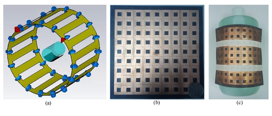
(a) The CST simulation model
of metamaterial inserted to a birdcage volume coil. (b) The manufactured
metamaterial with 9×9 cells. (c) The metamaterial bent on the phantom in phantom
experiment.
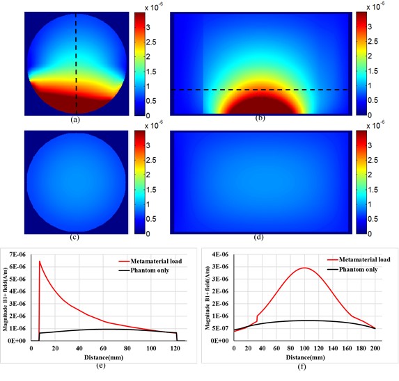
The B1+ field maps of the
phantom with metamaterial load in transverse (a) and sagittal (b) planes and
without metamaterial in transverse (c) and sagittal (d) planes for simulation. The
variations of B1+ field along the black dotted line in transverse (e) and
sagittal (f) planes. Results were normalized to the accepted power of 1W in simulation.
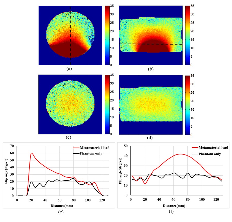
The B1+ maps of the phantom
with metamaterial load in transverse (a) and sagittal (b) planes for phantom
experiment and without metamaterial in transverse (c) and sagittal (d) planes
in phantom experiment. The variations of B1+ field along the black dotted line in
transverse (e) and sagittal (f) planes.