2673
An adjustable field-of-view rung element for 7T transmit array coils using forced current excitation1Electrical& Computer Engineering, Texas A&M University, College Station, TX, United States
Synopsis
This abstract reports a switchable coil element which uses “forced current excitation”. The coil consists of three aligned rungs, with a total length of 37 cm. Any one or more of three rungs can be easily selected to provide a variable length or position field-of-view. The forced current approach ensures equal current on the selected rungs to give a uniform field distribution along the length of the field-of-view. Bench measurements demonstrate the expected efficiency improvement when only a single rung is selected and the uniform field pattern.
Target Audience
Researchers and practitioners interested in RF coils for high-field MRI.Introduction
Spine imaging at 7T is of high interest due to the high intrinsic signal-to-noise ratio (SNR) and its diagnostic potential [1]. The large field of view (FOV) requires a long RF coil for surveying the spine. At lower field a body coil can be used for transmission with an array for reception. Most 7T system does not have a body coil. Additionally, at 7T it may be desirable to tailor the RF coil length such that only the desired portion of spine, e.g. cervical, thoracic or lumbar zone is excited while redundant power decomposition is avoided. Qi et al has reported a segmented coil design at 7T where the FOV can be adjusted to a certain degree [3]. However the design does not allow the user to select the FOV near the edge of the coil. Here we report a switchable length rung design using a very straightforward design, force current excitation, which can provide uniform field distribution as well as enhanced flexibility for varying the FOV. This concept has been demonstrated previously with a switchable unilateral/bilateral 7T breast coil [4]. In this work, the design is scaled to three elements on a 37 cm long rung intended for use in a spine coil.Methods
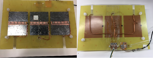
Forced Current Excitation uses odd multiples of ¼ wavelength transmission lines to excite coil elements and guarantee equal current delivery to different elements despite mutual coupling [5]. The other ends of the transmission lines are connected to the common voltage point, which can be upgraded to a PIN diode switching circuit to activate or detune each coil element [4]. Three short current rungs, 11cm each and with 2 cm gap between them, are aligned in the z direction to form a 37 cm long spine coil. Each rung is segmented every 2cm with a 33pF capacitor. A ground plane, serving as the current return path, lies 1.2 cm beneath each current rung. The rungs are fed from the side with ¾ wavelength coax cables with very low loss semi-rigid cable (EZ form-141). Three DC signals are generated from a power supply module to control the switching circuit: a +15V bias activates the corresponding rung, while a -15V bias detunes it. With the ability to enable or detune each of the three elements, the coil is equipped with eight different operating modes in total. Depending on the region of interest, the user can pick from any of the eight modes for imaging. The coil was tested on bench in four modes. With the same input power applied, the efficiency of the coil in the four modes were measured using a shielded probe and a network analyzer. The measurement was taken along z direction with 1cm resolution, at 4cm away from the coil in the y direction at 298 MHz, which is the larmor frequency at 7T.Results and discussion
The four modes being tested are left coil only (mode 1), middle coil only (mode 2), right coilonly (mode 3) and all coils (mode 4). The B1 maps were plotted together and scaled to the global maximum. Mode 4 demonstrate uniform excitation across a large FOV, which means equal current is achieved at each rung. Modes 1-3 demonstrate higher power efficiency in the corresponding area. The efficiency of mode 1-3 is 3.5-4 dB higher than that of mode 4, in the corresponding region. Additional modes, with two of the three rungs excited were possible but not presented. This work uses current rung as the basic element, however this method can be used for any type of coil element. In addition, the coil structure can be divided into more elements (more than three) if smaller FOV and higher B1 efficiency is required.Conclusion
Forced-current excitation is used to excite a three-element spine coil. It is also configured such that each small coil segment can be activated or detuned through electronic control, giving flexible FOV variation. A large FOV gives large coverage while a smaller FOV allows more focused RF power, potentially important in some applications requiring either low whole-body SAR or localized high B1 values. In addition, when multiple elements are activated, the FCE method ensures uniform current delivery to the different element and prevents mode splits due to coupling. This work also proves the scalability of the ‘FCE+variable FOV’ concept. This ‘extendable rung’ design will be used as the element in a two element spine array in the future.Acknowledgements
This work was supported in part by grants from the National Institutes of Health (R21HL120064 ) and the Cancer Prevention and Research Institute of Texas (RP15046 or RP160847).References
[1] Sigmund, E. E., et al. "High-resolution human cervical spinal cord imaging at 7 T." NMR in biomedicine 25.7 (2012): 891-899.
[2] Zhao, Wei, et al. "Nineteen-channel receive array and four-channel transmit array coil for cervical spinal cord imaging at 7T." Magnetic resonance in medicine 72.1 (2014): 291-300.
[3] Duan, Qi, et al. “Segmented Dipole: A Remotely Reconfigurable Near-Field Dipole Antenna Transmitter for Optimized 7 T Spine Imaging”. In Pro Intl Soc Mag Reson Med 2016; 3512.
[4] Cui, Jiaming, et al. "A Switched-Mode Breast Coil for 7 T MRI Using Forced-Current Excitation." IEEE Transactions on Biomedical Engineering 62.7 (2015): 1777-1783.
[5] McDougall, Mary P., et al. "A simple approach to overcoming mutual coupling effects in some transmit array coils for magnetic resonance imaging." 2008 30th Annual International Conference of the IEEE Engineering in Medicine and Biology Society. IEEE, 2008.
Figures