2672
Human Brain Imaging at 7T With On-coil Transceivers1Advanced MRI Section, LFMI, NINDS, National Institutes of Health, Bethesda, MD, United States, 2Food and Drug Administration, Silver Spring, MD, United States
Synopsis
On-coil current-source switch-mode amplification presents high power efficiency, allows direct control of the transmit field (B1), and decoupling of elements through the amplifier output impedance. These are important advantages over conventional remote voltage-mode quasilinear amplification that should allow more efficient and safer implementation of a multi-channel transmit system. Following this approach, we present an optically controlled transceiver design that was used for initial safety assessment of the technology toward the implementation of a high channel-count pTx array for brain imaging at high-field. We acquired human brain images with this technology at 7T
Introduction
On-coil current-source switch-mode amplification presents several advantages over conventional remote voltage-mode quasilinear amplification, namely high power efficiency, optical and direct control of the transmit field (B1), and decoupling of elements through the amplifier output impedance1,2. These advantages should allow more efficient and safer implementation of a multi-channel transmit system, and a significant simplification of the coil array. Based on our previous -300 MHz- amplifier design and pTx interface2, we built a transceiver array by adding a miniaturized transmit-receive (TR) switch and low-noise amplifier (LNA) to the on-coil configuration. A transceiver setup simplifies a first safety assessment toward imaging humans by eliminating the need of additional receive hardware. This early, if not first application of on-coil transceivers for MRI of in-vivo human brain was performed at low transmit power.Methods
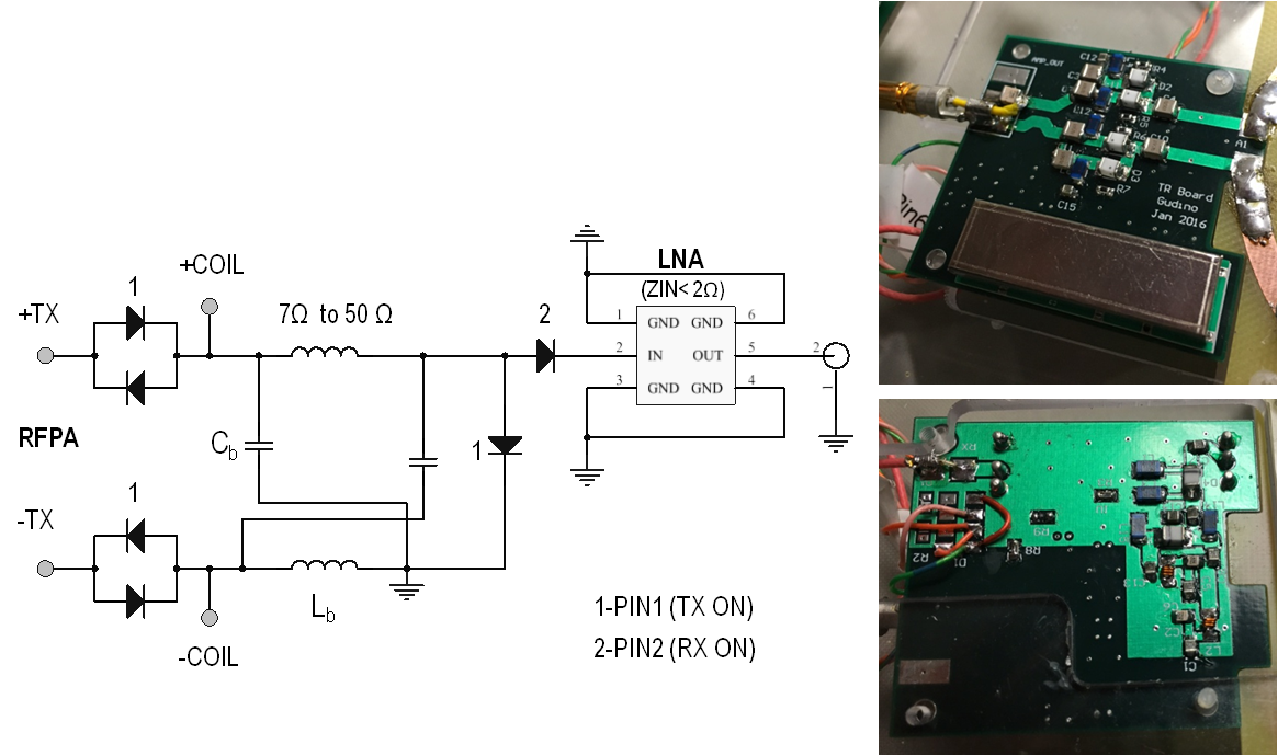
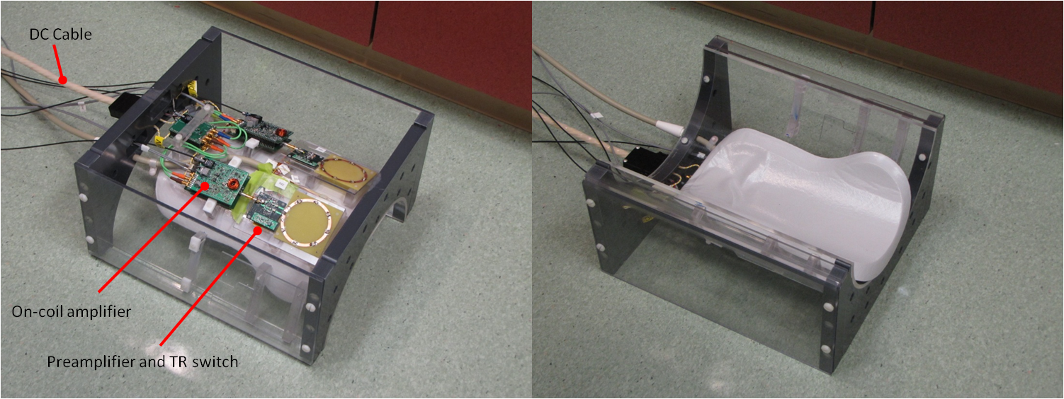
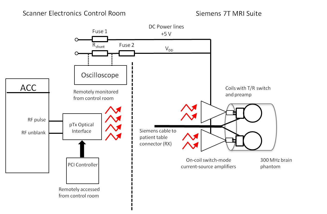
Hardware : Optically controlled on-coil amplifiers for 7T imaging2 were connected to 6 cm diameter loops through a 4.2 x 4.6 cm 5-layer double sided PCB that contains a miniaturized TR switch and an in-house LNA (Figure 1). The switch provides a balanced connection from the amplifier to the coil trough a pair of low loss PIN diodes and a balanced to unbalanced connection to the LNA through a 50 Ω lattice balun. Additional isolation was achieved by a PIN diode in series with the LNA. During transmission a pin diode shorts the balun output and high impedance is seen from the coil into the RX due to the double parallel resonance formed by the Cc-Lb pair. During signal reception the impedance transformation of the balun results in optimum impedance seen from the LNA into the coil (around 50 Ω) and element decoupling is provided by the low preamplifier input impedance (< 2 Ω) . In this preliminary work 2 channels were assembled on the outside of a half cylindrical former to electrically insulate all electronics from the volunteer while also providing head support (Figure 2). Phantom Imaging: Axial images of an oil phantom were acquired with a single transceiver element using a gradient-echo sequence with a rectangular RF pulse, TRF=4 ms, TR=2 s, TE= 3.18 ms, FOV=144 mm x 108 mm, resolution= 1.1 mm x 1.1 mm x 2 mm. SNR maps were calculated from these images. SAR simulations: Electromagnetic simulations were performed for two loops located at an azimuthal angle of 45 degrees and 3.7 cm separation, as assembled on the cylindrical former. Both elements were located 2.6 cm from a cylindrical phantom (f=16 cm and l=20 cm) that simulates brain tissue (σ=0.55 S/m and ε=52)3. The total average input power for computing the 10-g average SAR was limited to 0.4 W. SAR was computed while sweeping the phase of one channel in 45-degree steps. In-vivo brain imaging: The setup is shown in Figure 3. The optical interface and amplifier design have been detailed in our previous work2. The RX signal is sent to the scanner console through the coil connection on the patient table. This also provides the PIN diode signals and DC bias for the LNAs. In this initial experiment, peak power per amplifier was below 20 W by limiting the total DC input power to 40 W. Excitation duty cycle was limited to 1% to keep average total power below 0.4 W as it was limited for SAR simulations. Additional safety protections were added by monitoring DC input current and fuses in the power line. Images of a volunteer brain were acquired with a gradient-echo sequence, with a flip angl=10 degrees, TE/TR=7/500 ms, slice thickness =5 mm, FOV= 195 X 240 mm and matrix size= 286 X 352. Imaging was approved by the Institutional Review Board.Results
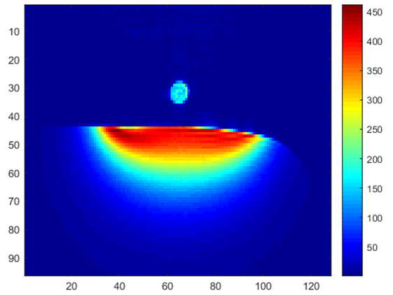
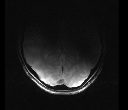
The TR switch provided 50 dB isolation to protect the LNA during transmission. Maximum SNR was above 400 for 80-degree nominal flip angle as shown in Figure 4. Noise images were acquired (RF amplitude =0) with and without the amplifier inside the bore. Less than 1% increase in the noise standard deviation was detected. The maximum local SAR10g obtained from simulations was at least 7 times lower than the FDA limit of 10 W/kg. Figure 5 shows a volunteer’s occipital brain region obtained by two-channel transmission and reception.Discussion
Successful practical high field
implementation of on-coil transceive technology was demonstrated on human
brain. Our on-coil transceiver setup allowed to simplify the safety assessment
and is easily extendable to a larger number of channels. We are currently
working on a four-channel array that includes real-time monitoring of the
transmit signal4 to
achieve higher performance and ensure safety under high power operation.Acknowledgements
No acknowledgement found.References
1- Gudino N, Heilman JA, Riffe MJ, Heid O, Vester M, Griswold MA.Magn Reson Med. 2013 Jul;70(1):276-89.
2-Gudino N, Duan Q, de Zwart JA, Murphy-Boesch J, Dodd SJ, Merkle H, van Gelderen P, Duyn JH.Magn Reson Med. 2016 Jul;76(1):340-9.
3-Duan Q, Duyn JH, Gudino N, de Zwart JA, van Gelderen P, Sodickson DK, Brown R. Med Phys. 2014 Oct;41(10):102303. doi: 10.1118/1.4895823.
4- Gudino N, de Zwart Jacco A., Duan Qi, van Gelderen Peter, and Duyn Jeff H. Proc. Intl. Soc. Mag. Reson. Med 24, 2016 (Abstract 2181)
Figures