2671
New design of flexible surface coil with variodes and remote detuning1RF-R&D, Siemens (Shenzhen) Magnetic Resonance Ltd., Shenzhen, People's Republic of China, 2R&D, Siemens (Shenzhen) Magnetic Resonance Ltd., Shenzhen, People's Republic of China
Synopsis
New design of flexible surface coil was presented. Voltage-controlled variodes instead of trimmers are used for remote coil frequency adjustment; λ/4 impedance transforming circuit are used to enable remote detune, thus detune circuits with big rigid components are moved out from the antenna part. By doing this, the antenna is covered by soft foam seamlessly which improved the flexibility significantly. Design was tested on four-element arrays. Experiments on both phantom and invivo testing show good results with this design.
Purpose
Surface coil array improves SNR without imaging time increasing[1]. Flexible surface coil array is a research focus because it can conform to different body shapes closely for optimum filling factor, thus best image quality. Meanwhile it could replace anatomy-dedicated rigid coils which from economic point of view is a good choice. Corea J, et al demonstrated fully printed MRI coils [2, 3] to improve SNR by puting the antenna closer to patient. Currently it is difficult to make the antenna part fully flexible, because trimmers are needed for coil tuning and big inductors with high Q value are needed for coil detuning; thus rigid covers can not be avoided to allow tuning and for protection. A example with traditional design is shown in figure 3 (b). In this abstract, we presented a new design for flexible surface coil which could helps to overcome those shortages. It helps to improve antenna flexibility significantly; meanwhile without compromise on image quality.
Methods
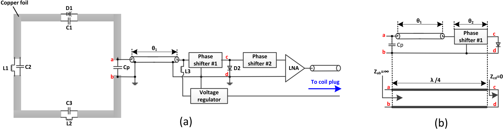
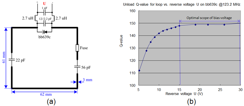
The schematic of a single coil element with the new design is shown in Fig.1 (a). In antenna part, copper foils are printed on a flexible PCB, and lumped capacitors, inductors and diode are soldered on copper foils. Voltage-controlled variode D1 is used to do frequency adjust remotely together with voltage regulator instead of traditional capacitor trimmer. To reduce quantity of electronic components in antenna part as less as possible, λ/4 impedance transforming circuit is used for coil active detune instead of traditional parallel resonant inductor and capacitor. Capacitor Cp, 50 Ohm coax with electronic length θ1 and phase shifter #1 with electronic length θ2 forms the λ/4 impedance transformer, which convert impedance viewed from point a and b to infinity (Zab=∞) when PIN diode D2 is turned on (Zcd=0) by a constant current during Tx phase, as seen in Fig.1 (b). During coil receive phase, PIN diode D2 is biased with a negative voltage so that it is break down, then phase shifter #2 moves phase to match LNA for pre-amplifier decoupling. Inductors L1, L2 and L3 are RF chokes used for DC voltage through for variode D1.
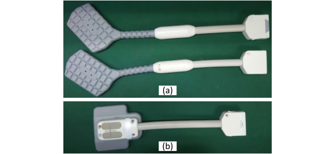
The new design was implemented on two four-element surface coil arrays. Fig.3 (a) shows the photo of the prototype coil. As a comparison, a reference prototype coil with traditional design was also build, as seen in Fig.3 (b). For the reference prototype coil, the frequency tuning is by capacitor trimmer and active detune is by parallel resonant capacitor and inductor, so there is rigid mechanical cover in antenna part which is much less flexible. All prototype coils have four coil elements with same antenna layout and size. The total size of antenna is about 110 mm X 74 mm.
Results
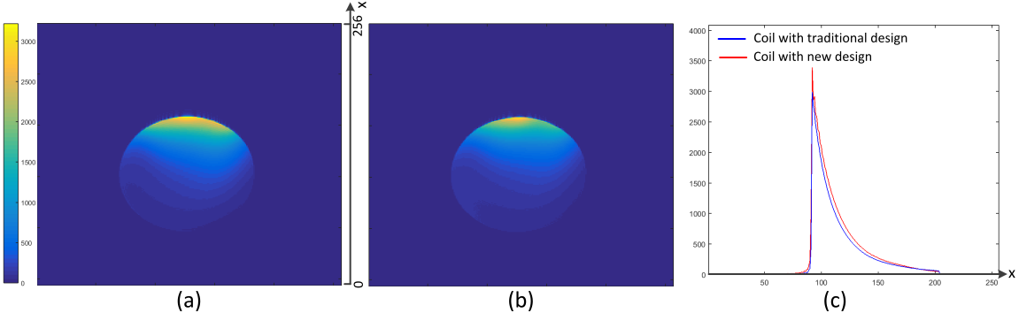
SNR comparison between reference prototype coil and prototype coil with new design presented in the paper was performed on a 5700 mL phantom in Siemens MAGNETOM Spectra system. Due to the same antenna layout and size, profiles and SNR of phantom image received by two coils are near the same, as seen in Fig.4 (a) and (b). While, at the phantom surface near to coil, SNR received by prototype coil with new design is a little higher than reference prototype coil, as seen in Fig.4 (c). This is because the antenna of prototype coil with new design is much more flexible so that it can conform to phantom more closely.
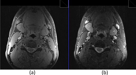
Clinical images were also measured on invivo for two prototype coils with new design in Siemens MAGNETOM Verio system. The two coils were placed on left and right carotid respectively. As seen in Fig.5, the SNR of image from carotid is very good whether for T1 weight or T2 weight.
Conclusion
We have presented a new design of flexible surface coil and implemented the design to four-element coil prototype. Compare to coil with traditional design, the antenna part of prototype coil is much more flexible, meanwhile the SNR is comparable. Clinical image evaluation(special on carotid evaluation) also shows good results.Acknowledgements
We would like to acknowledge Siemens Healthineers Collaboration China and US team for clinical evaluation supporting.References
[1] Romer PB, et. al, The NMR phased array, Magnetic Resonance in Medicine 16, 192-225 (1990).
[2] Lechene PB, Corea J, et. al, High-quality flexible printed MRI receive coils towards garment integration, ISMRM 2016.
[3] Corea J, et.al, Screan printed flexible 2-channel receive coil array, ISMRM 2012.
Figures