2667
Towards Routine Body Imaging at 7T Using a Hybrid Dipole and Birdcage Coil Array1Center for Biomedical Imaging, Department of Radiology, NYU School of Medicine, New York, NY, United States, 2Center for Advanced Imaging Innovation and Research (CAI2R), NYU School of Medicine, New York, NY, United States
Synopsis
Body imaging at 7T is challenging due to wavelength effects, a low sensitivity in deep tissue1, and a large variation in body sizes across the patient population. A common approach is to use close fitting coils or dipoles2,3,4, which exhibit a high transmit and receive sensitivity and are fairly load independent, but lack the easy handling necessary for routine clinical use. We aim to construct an RF coil array for general purpose body imaging for routine use that is robust, easy, and safe to handle, while retaining adequate sensitivity in the deeper regions. Given these boundary conditions, we settled on a stand-off design5 with an RF shield. Thus, consciously sacrificing some sensitivity to improve handling and safety. After extensive optimization we converged to an optimal coil array consisting of a transceive dipole array complemented with a birdcage array for reception only. The array was completed and a sensitivity analysis with respect to body sizes was performed.
Introduction
Body imaging at 7T is challenging due to wavelength effects, a low sensitivity in deep tissue1, and a large variation in body sizes across the patient population. A common approach is to use close fitting coils or dipoles2,3,4, which exhibit a high transmit and receive sensitivity and are fairly load independent, but lack the easy handling necessary for routine clinical use.
We aim to construct an RF coil array for general purpose body imaging for routine use that is robust, easy, and safe to handle, while retaining adequate sensitivity in the deeper regions. Given these boundary conditions, we settled on a stand-off design5 with an RF shield. Thus, consciously sacrificing some sensitivity to improve handling and safety. After extensive optimization we converged to an optimal coil array consisting of a transceive dipole array complemented with a birdcage array for reception only. The array was completed and a sensitivity analysis with respect to body sizes was performed.
Methods
In a previous work6 we outlined the reasoning behind the proposed design, the optimization of the coil array, parts of the construction, and initial phantom experiments.
As previously described6, we decided to target the 50 percentile of male patients and smaller. We decided for a rigid, stand-off design for load stability with respect to body size, patient and handling comfort. The coil elements are placed equidistantly from each other on an ellipse, ensuring a high sensitivity throughout the transversal plane. The top half of the coil can be detached for easier access for the patient. An RF-shield is used for patient safety maintaining the RF field inside the RF-shield and in the coaxial cables, preventing cable currents, and matching instability due to cable routing.
To improve handling we have now incorporated the TR boards for the dipole sub-array, including on board preamplifiers, into the coil housing, added dedicated ODU connectors to provide a clean interface with the MR system, and completed the 3D-printed outer housing to protect the subject and the electronic circuitry.
The coil elements are matched to the appropriate impedances for the transmit and receive case, on a body sized phantom filled with tissue simulating liquid. An appropriate phase shifter was used to transform the high reflection coefficient of the preamplifier to a high impedance at the feed point of the coil elements for preamplifier decoupling. This matching condition was kept constant throughout all experiments. A safety assessment was performed experimentally for the imaging experiments7 yielding a power limit of 20W/10s (total power).
We performed a series of volunteer experiments to investigate the sensitivity of the array with respect to body sizes. A total of three volunteers participated in the study, each with a different body mass index (18 (small), 23 (medium), and 28 (large)). Scattering matrices were measured on the bench with an eight channel network analyzer, Keysight. The imaging experiments were performed on MAGNETOM 7T MRI system (Siemens, Healthineers, Erlangen, Germany). B1+, and SNR-maps were acquired.
Results
B1+ maps for the different body sizes are shown in Fig2, scattering matrices in Fig3, SNR-maps in Fig4 and noise correlation matrices in Fig5.Conclusion & Discussion
A potential workhorse coil for body imaging at 7T is presented. patient friendly, easy to handle, and safe. A rigid, stand-off design that can be split for easy access was chosen, for patient comfort and easy handling. A safe and predictable operation is ensured by using an RF shield in conjunction with lattice baluns. A high sensitivity and homogeneity was achieved for a broad range of body sizes, without the need to rematch the coil elements for different body sizes.
Future work includes a safety assessment based on simulation including a body model for a less conservative power assessment, based on virtual observation points.
Acknowledgements
No acknowledgement found.References
[1] Hoult D I, JMRI 12: 46-67 (2000)
[2] Raaijmakers AJE, MRM 66(5): 1488-1497 (2011)
[3] Wiggins G, ISMRM 23: 2737 (2013)
[4] Ertürk MA, MRM: DOI:10.1002/mrm.26153
[5] Orzada S, ISMRM 24: 0167 (2016)
[6] Paska J, ISMRM 24: 2134 (2016)
[7] Cloos M, ISMRM 21: 0286 (2013)
[8] Cloos M, Nature Communications 7: doi:10.1038/ncomms12445 (2016)
Figures
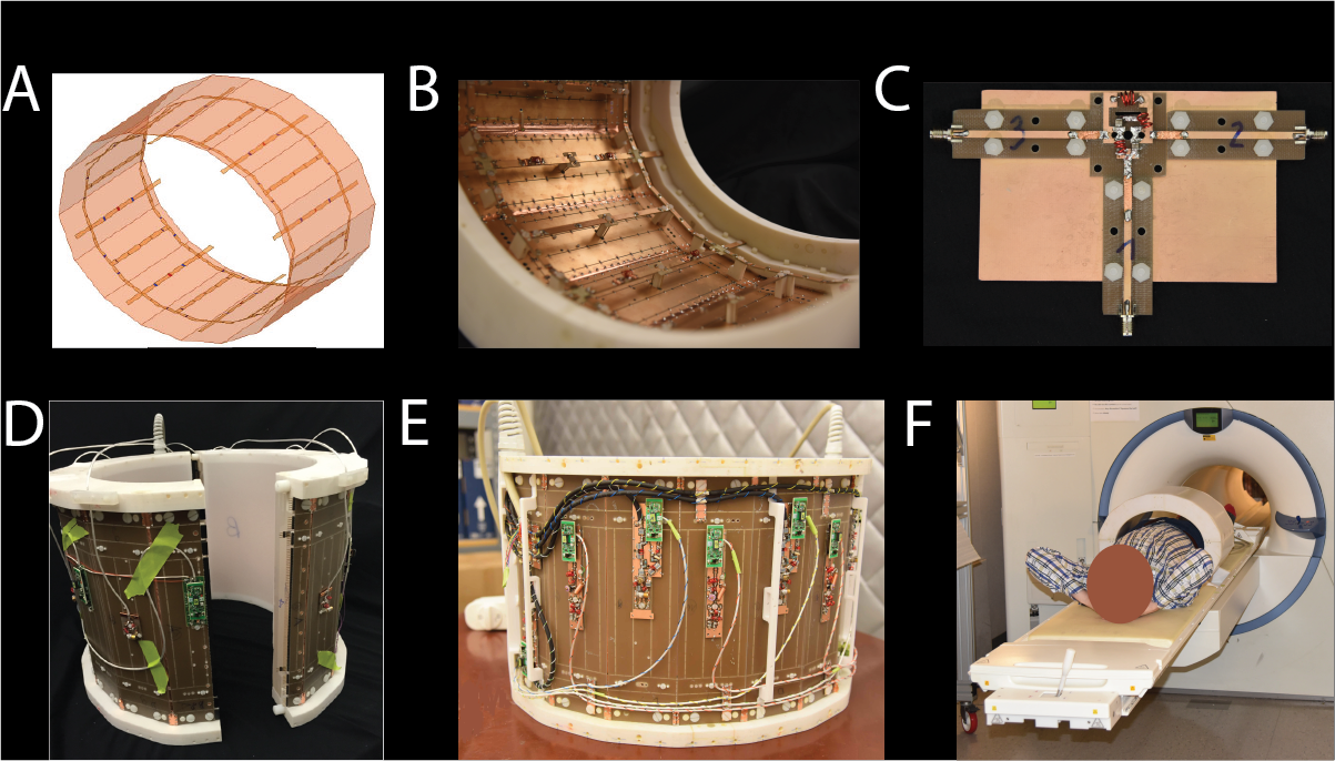
Fig1: Construction and setup of the coil array. (A) Array setup, 8 dipole elements interleaved with a birdcage array with 8 rods, with a RF shield. (B) Design based on PC boards, and a 3D printed holder. Feeding with a two-wire line in the center of the dipoles and the rods of the birdcage. (C) Lattice balun adjustment setup. (D)Array can be split for easier access. (E) The two wire line is routed behind the RF-shield and transformed to a unbalanced signal through the lattice balun. On-coil preamplifiers, detuning, and TR-switches.(E) Coil array with outer housing in the MR scanner.
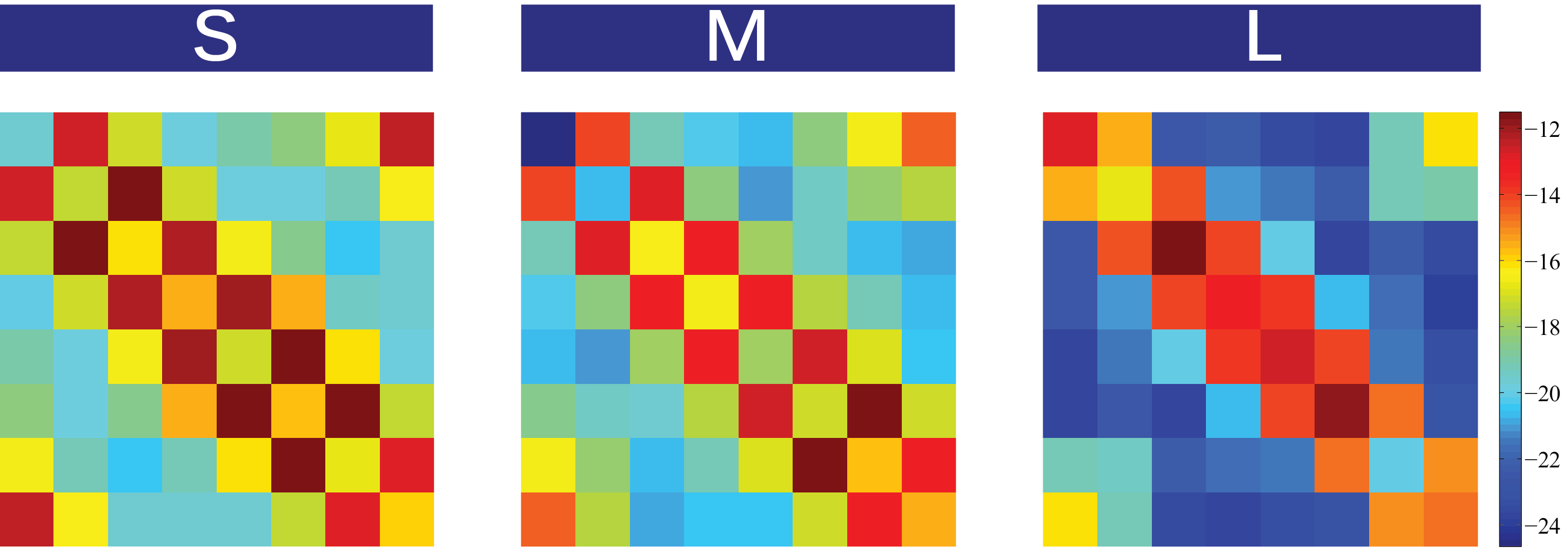
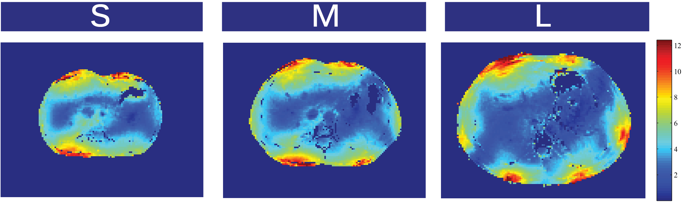
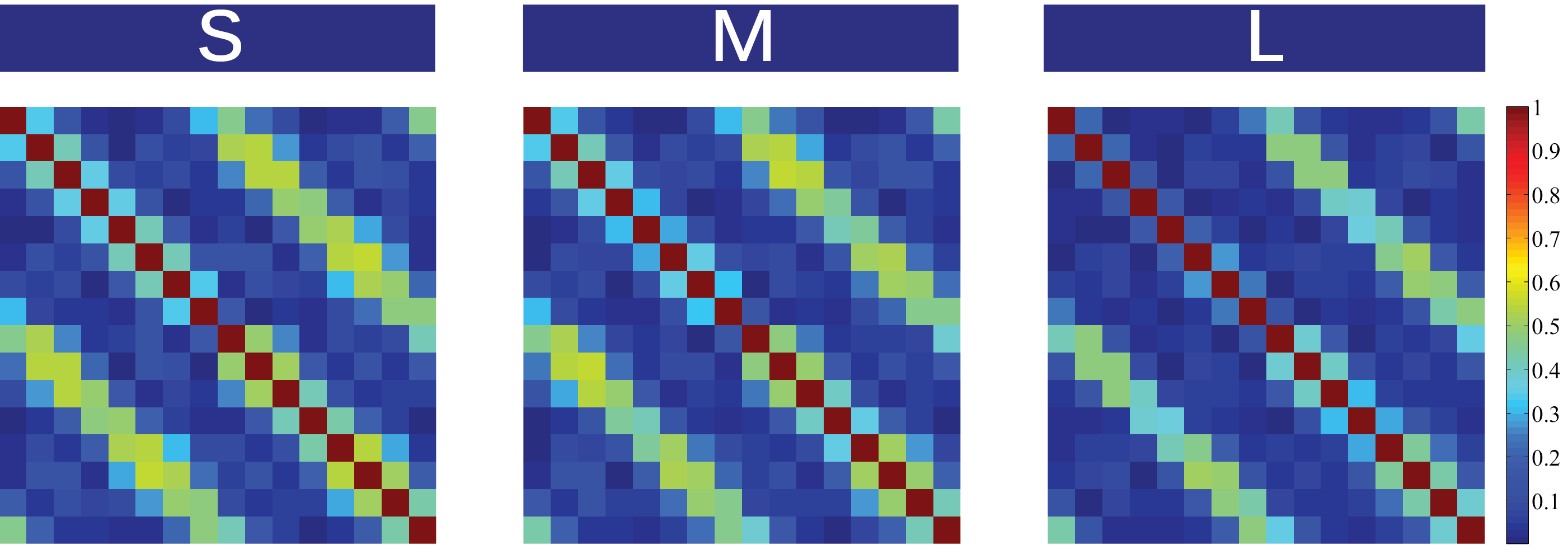
Fig4: Noise correlation matrices of the hybrid 16 channel array for different body sizes. Measurements were performed for a small (S), medium (M), and large (L) volunteer corresponding to body mass indices of 18, 23, and 28 respectively.
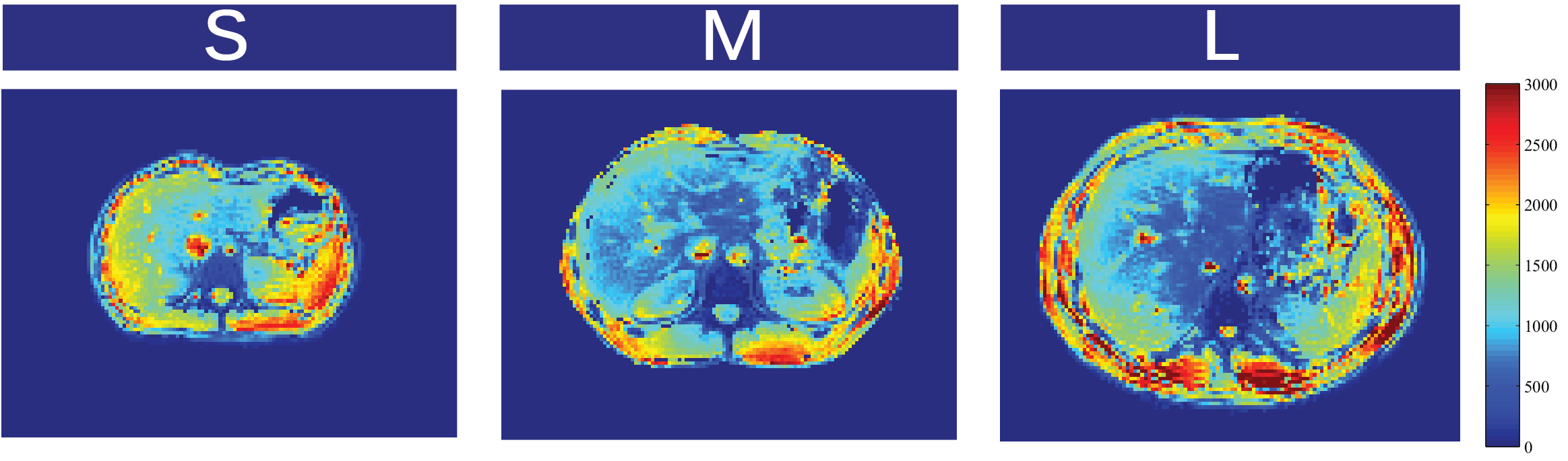
Fig5: SNR for different body sizes. Measurements were performed for a small (S),medium (M), and large (L) volunteer corresponding to body mass indices of 18,23, and 28 respectively. Measurements were performed for a small (S), medium(M), and large (L) volunteer corresponding to body mass indices of 18, 23, and28 respectively. Receive signal maps of each individual channel with a smalltip-angle GRE breath hold sequence were acquired (FA=15,TR=200ms,128matrix,Taq=30sec). Noise correlation matrices were calculated, and optimal reconstruction was used to compute the images[]. The resulting signal map was normalized with the sine of the flip angle distribution to remove the transmitfield bias.