2665
Dual-Tuned RF Coil system for Parallel Imaging of Human Lungs Using Perfluorinated Gases1ScanMed, LLC, Omaha, NE, United States, 2Duke University, Durham, NC, United States
Synopsis
To create a dual-tuned (1H & 19F) receive-only surface coil array for pulmonary functional imaging. This satisfies an unmet clinical need because there is currently no widely accessible 3D measure of regional lung function. As a result, the current standard of care for diagnosis and evaluation of lung disease relies nearly exclusively on global measures such as spirometry. The technical significance of this proposal is that the implementation of parallel imaging for 19F MRI would provide a means to shorten breath hold times with marginal SNR impact as well as facilitate the development of real time free breathing image acquisitions.
Purpose
This abstract is a continuation of the study demonstrated in the 2015 ISMRM e-poster# 3984. The conclusion of the 2015 study was that the implementation of parallel imaging with a receive-array 8-element array coil tuned at 19F frequency with a dedicated 19F transmit coil provided good S/I coverage, excellent image uniformity, adequate SNR, and good image quality even in subjects with severe lung disease with 3D imaging times < 6 seconds. The future direction described in 2015 was to implement a dual tuned higher density receive-only surface coil array in order to further improve the temporal resolution.
The major challenge to overcome was to create dual frequency capabilities without comprising data quality. Specifically, improving SNR for the 19F component while still improving the 1H SNR over the body coil transmit/receive option currently implemented with the previous 8 channel array. The first step was to build a coil that on the bench provided good scattering (S) parameters; and the second, provide excellent phantom SNR for the elements 19F and 1H which are close-by in frequencies, i.e. 115.9MHz and 123.2MHz respectively at 3 Tesla (Siemens TIM Trio). In this abstract, we are presenting a 2 channel dual-tuned coil implementation that meets both these challenges.
In the past researchers, have disclosed a variety of dual tuned circuits1,2,3,4. Strategies include resonant traps in-line with capacitors or switches such as MEMS, varactors, or PIN diodes in-circuit to shift the resonant frequency of a RF coil element and to maintain the low input impedance characteristic of the RF coil preamplifier. What differentiates the current circuit is that it utilizes varactors not only for coil tuning and to adjust the low input impedance characteristic of preamplifier but it also adjusts the output impedance of the preamplifier. We found that is necessary to adjust the output impedance because a preamplifier tuned at 50 ohms (SWR 1.0) for the 19F frequency will give an output impedance of 21-5j ohms (SWR 2.5) for 1H frequency. This high SWR mismatch of preamplifier output impedance will result in substantial loss in SNR. In addition, to complicate the circuitry, there is a need for multiple active decoupling and passive decoupling networks at both frequencies in a single element as the coil should be safe in normal condition and single fault condition as it is meant for human imaging.
Methods
We constructed a receive-only dual-tuned (1H & 19F) surface coil with two overlapping elements with low-input impedance preamplifiers. Figure 1 shows the location of varactors at multiple locations to perform the frequency switching.
We were able to obtain excellent characteristics on the bench. At both frequencies, using Siemens NiSO4 + NiCl2 phantom cylinders, we obtained a ratio of unloaded Q to loaded Q of ~ 4.5. The preamplifier output impedance SWR for 19F frequency was at 1.1 and for 1H frequency was adjusted using varactors to give SWR of 1.5. Further, critical overlap was achieved such that the tuning peaks at both frequencies were clean Gaussian curves, hence, there was no element-element coupling (Figure 2).
The coil was then tested on the 3T Siemens MRI scanner in conjunction with the existing Duke University 19F transmit coil constructed for the 2015 study.
Results
As expected the SNR of the dual tuned coil at 1H frequency was higher than the 1H body coil scanned with the doped water phantom (Figure 3). Duke’s 19F lung phantom images in Figure 4 showed improved SNR proximal to the elements as would be expected but also demonstrate SNR comparable to the 19F tuned 8 channel coil at depth. These results suggest that the 16-element dual tuned strategy will be successful.
Conclusion
We created a 2-element receive-only dual tuned coil with excellent bench performance that when scanned in conjunction with a dedicated 19F transmit coil gave comparable SNR at 1H frequency when compared to the body coil and comparable SNR at 19F frequency when compared to the 8 channel receive-only 19F coil.
The future is to extend the 2-element circuit implementation to create a 16-element dual tuned coil for parallel imaging benefit, and incorporate the coil in ongoing human studies at Duke. A 16-element coil is the optimal solution for assessing lung airspace function using perfluorinated gases as contrast agents based on the feasibility analysis performed using standard modeling tools of field sensitivity profiles associated with 3D geometries and validated with SNR studies using an anterior/posterior coil.
Acknowledgements
No acknowledgement found.References
1. Troop, James S. Dual-frequency coil array for a magnetic resonance imaging system. U.S. Patent 8193811 B2 filed May 9, 2009, and issued June 5, 2012.
2. Devries, John T. Bandwidth expansion coil resonance. U.S. Patent 8030932 filed Aug 23, 2010, and issued Oct 4 2011.
3. Bulumulla, Selaka Bandara. Multi-nuclear receiving coils for magnetic resonance imaging. U.S. Patent 20140184217 filed Dec 27, 20012, and issued July 3, 2014.
4. Mansfield P, Coxon R. Coil Circuits. U.S. Patent US5325060 filed May 24, 1991, and issued June 28, 1994.
Figures
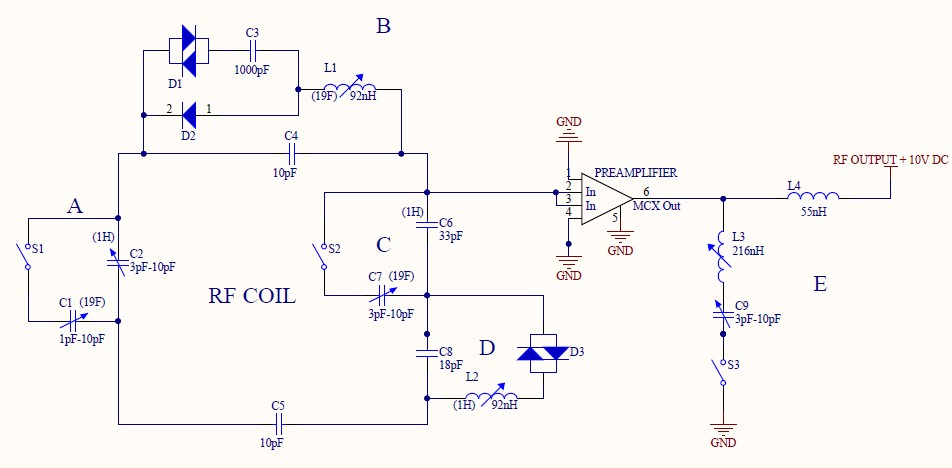
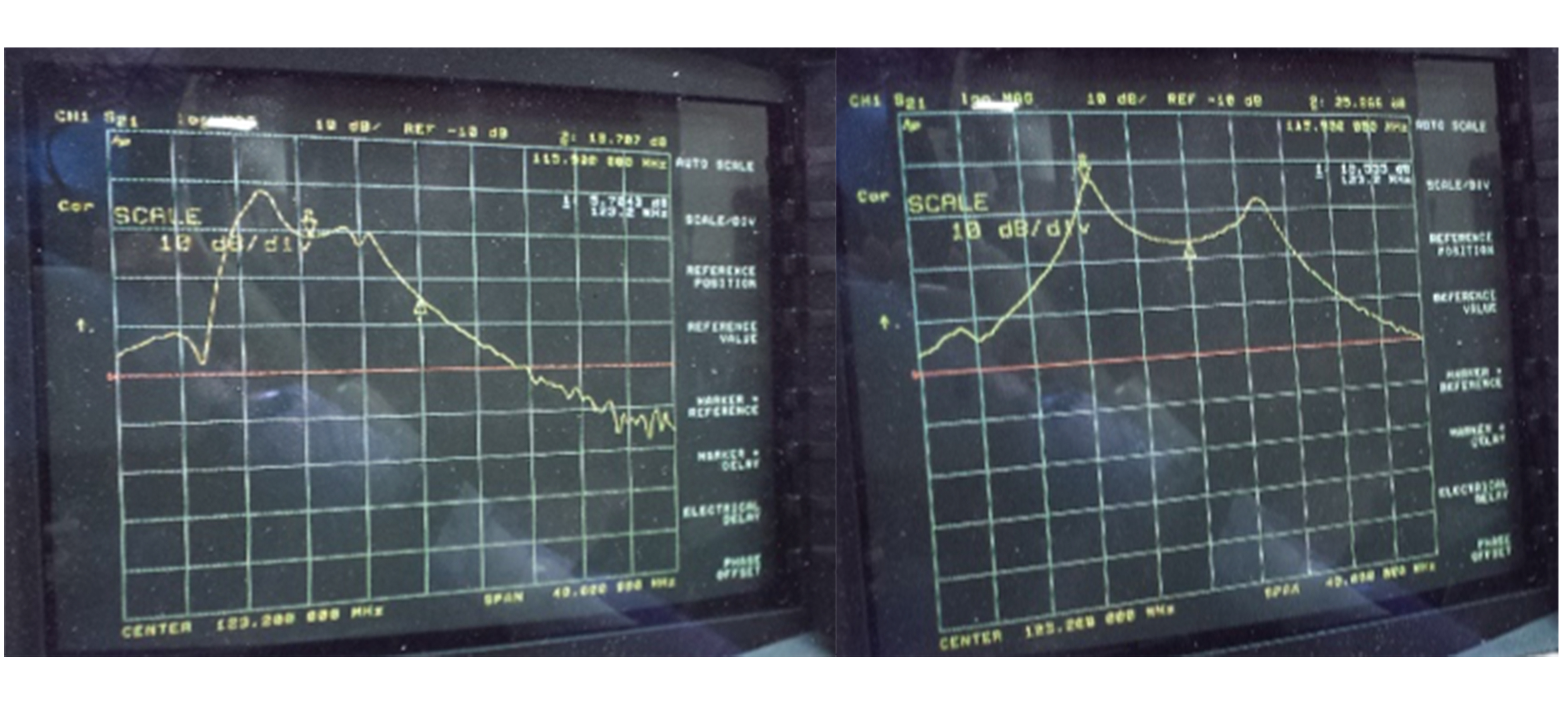
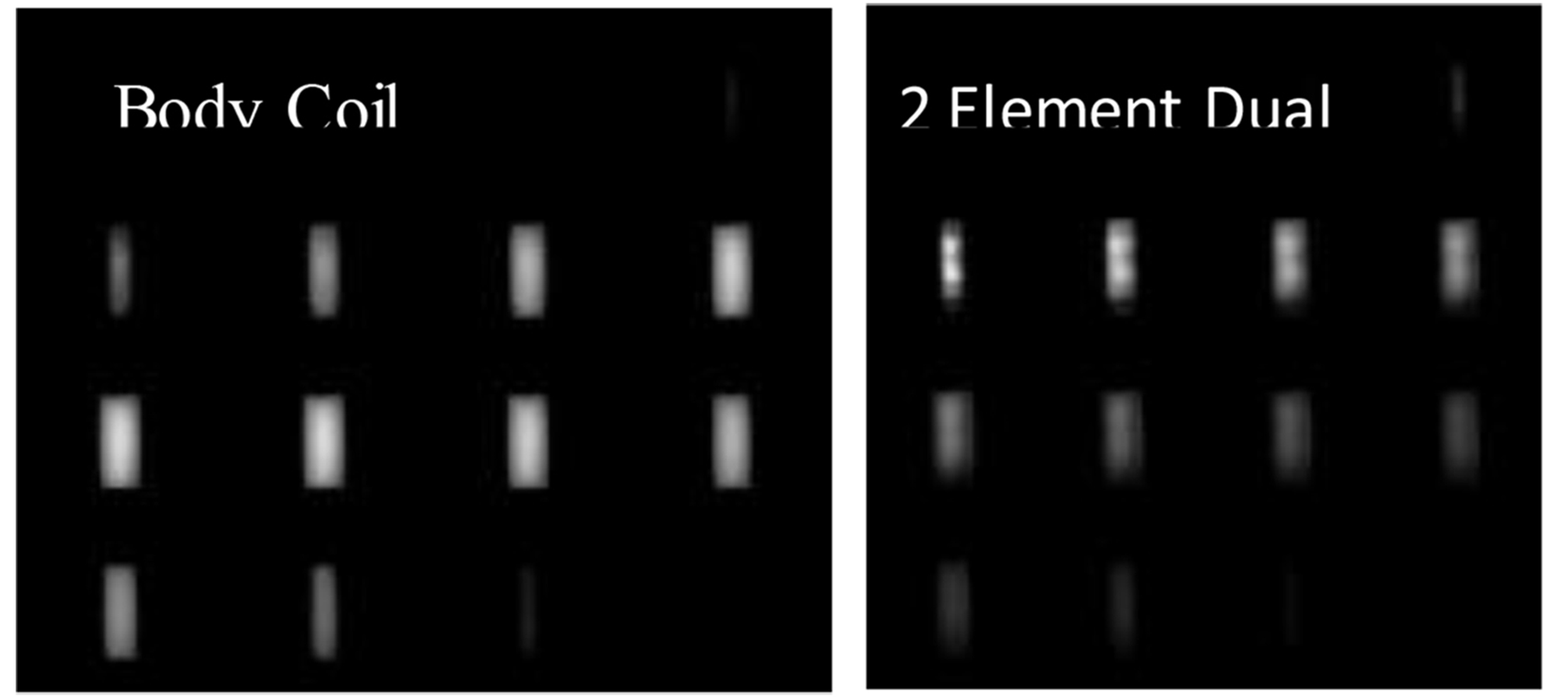
Figure 3: Example of BC (L) and A1, A2 (R) array prototype 1H images double coil. Each frame is one coronal slice of the 3D volume.
For all images, window was set from 0 to 1000. Each frame is one coronal slice of the 3D volume.
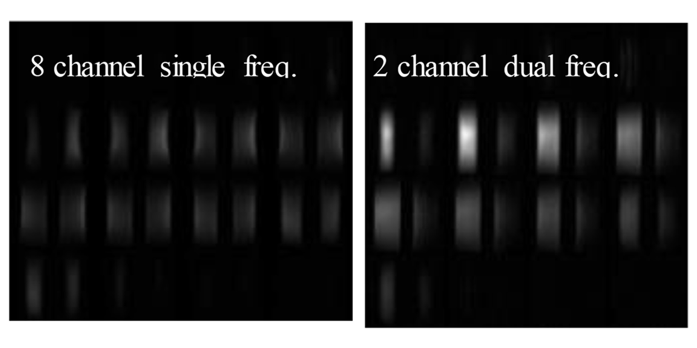
Figure 4: 8 element 19F single tuned array coil (L) and 2 element dual tuned array coil on the Duke’s lung phantom.
For all images, window was set from 0 to 1000. Each frame is one coronal slice of the 3D volume.