2664
Quadrature Head Coil for Brain Imaging at 6.5 mT1Department of Radiology, MGH/AA Martinos Center for Biomedical Imaging, Boston, MA, United States, 2Harvard Medical School, Boston, MA, United States, 3Department of Physics, Harvard University, Cambridge, MA, United States
Synopsis
Highly-resolved proton imaging is challenging in the millitesla regime. With the aim of enhancing our previous single-channel spiral head coil for operation at 276 kHz, a quadrature head coil was designed, comprised of 2 layers (inner and outer) producing orthogonal B1 fields. Images acquired with the new quadrature coil had the same signal magnitude when compared to the single-channel coil. However, the expected √2-factor signal enhancement in combined SNR was not fully realized due to a 30% higher noise floor observed in one quadrature. Improvements in gradient amplifier filtering will significantly improve the SNR.
Introduction
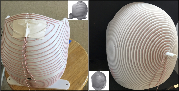
We describe here a new transmit/receive quadrature volume head coil design for ultra-low field (ULF) brain imaging at 6.5 mT (276 kHz) (Figure 1). Proton imaging in this regime is challenging mainly due to intrinsically low Boltzman polarization at ULF. Our past work using a one-channel spiral volume head coil has enabled 3D proton-density weighted brain images of 2.5 × 3.5 × 8.5 mm3 spatial resolution to be acquired in 6 minutes (NA=30) with good image quality1,2. Here, we improve the efficiency of the one-channel spiral volume coil by adding a second receiving coil orthogonal to the spiral layer. Theoretically, this addition of the channel will increase the SNR by a √2-factor3, thus allowing less averaging to be performed and shortening scan time.Materials and Methods
Coil description: The quadrature helmet former was designed using CAD software (Autodesk Inventor Professional, 2013, Autodesk, San Rafael, CA, USA) so that it fits 95% of human heads1,2. It is made up of two nesting layers — an inner 30-turn spiral based coil resulting in a B1 field in the axial (x) direction and an outer coil consisting of orthogonal loops with a resultant B1 field in the anterior-posterior (y) direction. Both B1 fields are orthogonal to the B0 z-axis. As in the previous single-channel spiral coil, resistive losses in our Johnson-noise-dominated coil were minimized with the use of stranded Litz wire (Type 1 5/39/42, New England Wire Technologies, NH, USA) for both layers.
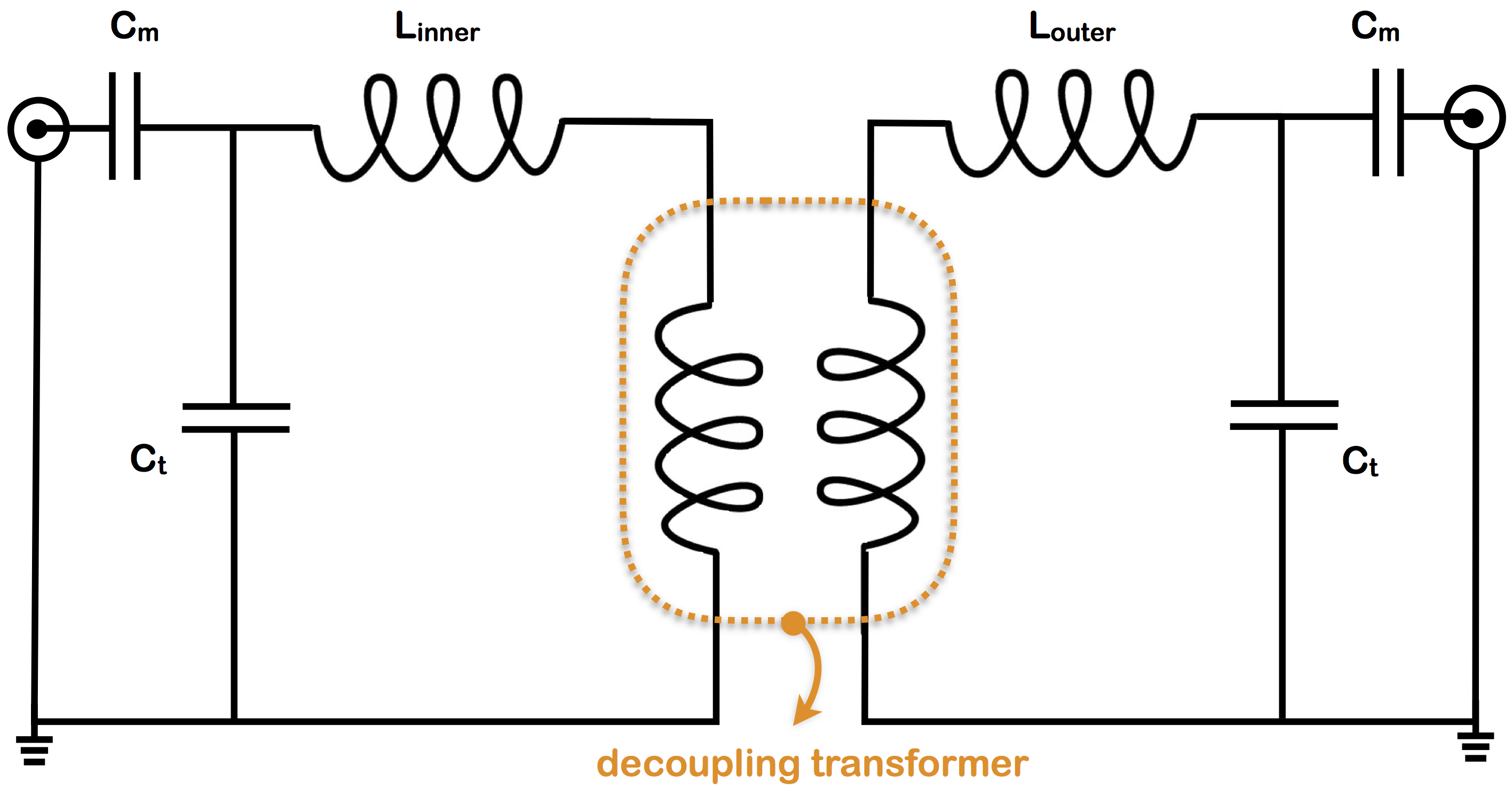
Each layer was tuned to 276 kHz, and matched to an S11 of at least –35 dB, and was then evaluated individually for imaging. The Q of the inner coil was 40 (BW=6.9 kHz) and of the outer coil was 53 (BW=5.2 kHz). After evaluation, the two layers were assembled together, and incomplete geometric decoupling resulted in some inductive coupling between the channels. An air-core transformer (Figure 2) was added in the circuit to null this mutual coupling. Both coils were geometrically decoupled by at least –15 dB (S12 parameter).
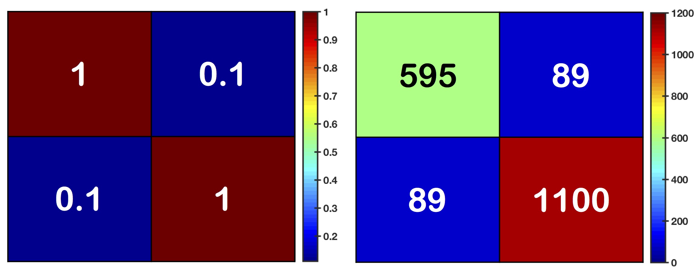
Imaging: A hemispheric water-filled structured resolution phantom2 was placed inside the coil. The combined quadrature head coil was placed in our ULF MRI scanner, with the outer coil was connected to the passive T/R switch and the inner coil was connected directly to a second receiver channel. A 3D b-SSFP sequence was used with a 50% undersampling ratio and voxel size of 3.9×2.5×5 mm3. Noise correlation and covariance for the two-channel array are calculated using noise vectors acquired by the loaded coil with the transmit RF voltage set to zero. Raw data was reconstructed with the sum of squares method from both channels and compared to the previous single-channel spiral head coil.
Results
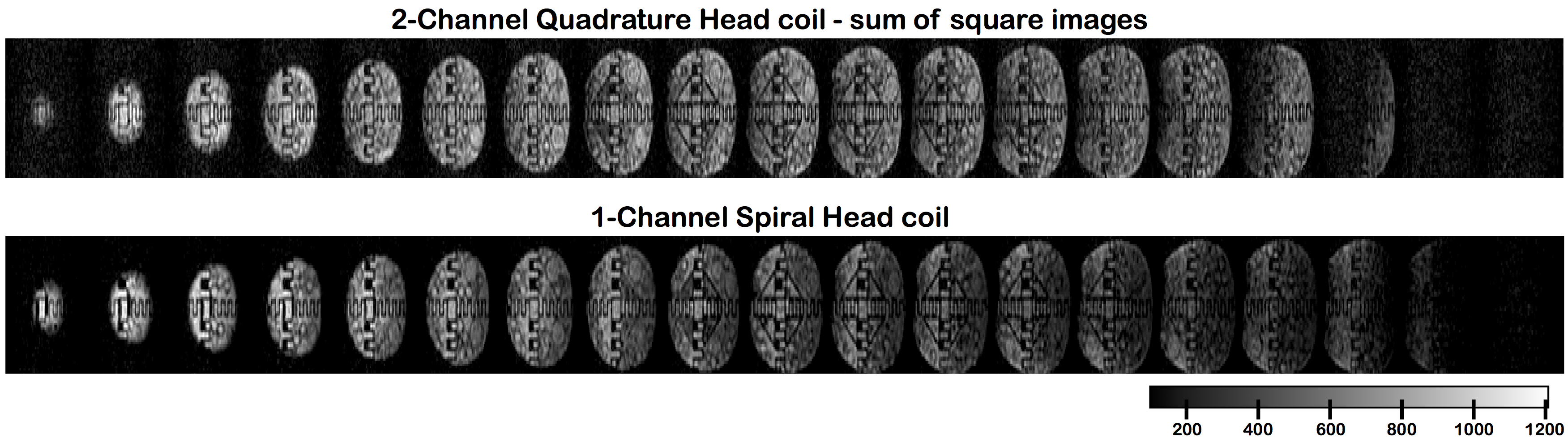
Images acquired at 6.5 mT with the inner layer coil have a maximum SNR of 51.5 (NA=10), as compared to a maximum SNR of 50 for our previous one-channel spiral head coil. However, despite the absolute signal magnitude obtained with the outer layer being essentially equal to that from the inner layer, the images were of poor quality owing to a high noise floor. In our scanner, poor gradient filtering results in broadband noise from the GPA entering the scanner. This increased noise floor is particular prominent in inductive detection along the y-direction, adding significant noise to detection with the outer quadrature. The noise correlation coefficient matrix was evaluated (Figure 3). SNR of the images were measured and compared to our previous one-channel spiral coil. Figure 4 illustrates 19 slices of the structured resolution phantom acquired with the quadrature coil versus the one-channel coil. The maximum combined SNR for the quadrature coil was of 64.8 (NA=30). In contrast, the maximum SNR measured with the previous one-channel spiral coil was of 81.5.Discussion and Conclusion
Equivalent overall image quality was obtained from the new quadrature head coil as the single-channel version, however the SNR was not improved. The outer quadrature has a 30% higher noise floor owing to inductively detected noise from incomplete filtering of the high current lines from the Y-gradient amplifiers. Work to improve the noise floor through higher performance filters is in progress. Conclusion: We have demonstrated a new quadrature head coil for use at ULF. Reducing the scanner noise floor will allow us to accelerate overall imaging, as signal size is essentially equal in both quadratures and we see no reason not to gain the √2- factor increase in combined SNR.Acknowledgements
No acknowledgement found.References
1. ‘Low-Cost High-Performance MRI’, M. Sarracanie, C. D. LaPierre, N. Salameh, D. E. J. Waddington, T. Witzel and M. S. Rosen, Scientific Reports 5 15177 (2015)
2. ‘A single channel spiral volume coil for in vivo imaging of the whole human brain at 6.5 mT’, C. D. LaPierre , M. Sarracanie, D. E. J. Waddington and M. S. Rosen, ISMRM abstract Proc. Intl. Soc. Mag. Reson. Med. 23 (2015) 5902
3. ‘Quadrature detection in the laboratory frame’, D. I. Hoult, C.-N. Chen, V. J. Sank, Magnetic Resonance in Medicine 1 339–353 (1984)
Figures