2663
Ladder and Overlapped Phased Array Coil Comparison for Neck Imaging at 3 Tesla1Radiology and Imaging Sciences, University of Utah, Salt Lake City, UT, United States
Synopsis
A ladder and overlapped phased array coils were constructed with the same number of channels and overall dimensions to see how much of a SNR performance difference there was between the two coil construction techniques. The results show that between 2 and 12 cm within a cylindrical phantom the difference between SNR was less than 3%. With negligible performance difference the ladder array can be a viable alternative to overlapped arrays if a simpler coil construction process is desired.
Purpose
Most surface coil arrays utilize Roemer’s method of coil design by using overlapped coil elements to increase field-of-view (FOV)1. Overlapping coils is the most common method of minimizing mutual inductance, but in our experience coils built with this decoupling approach are more difficult and time consuming to build than coils built with capacitive decoupling. However, because there are no seminal papers, to our knowledge, comparing overlapped phased array coil designs to capacitive decoupled ladder array coil designs, the performance difference between these two types of decoupling techniques is not known. For example, for a coil design using capacitive decoupling, as presented by Beck et al.2, would there be an SNR improvement if the coil array were constructed using overlapping loops for the same overall coil dimension? The same overall dimensions are considered because some applications require a former size and shape that can’t be modified. To answer this question we compared the SNR performance of a ladder array to an overlapped phased array, having the same overall dimensions. The imaging experiments were performed on a cylindrical phantom to represent Beck’s neck imaging coils2.Methods
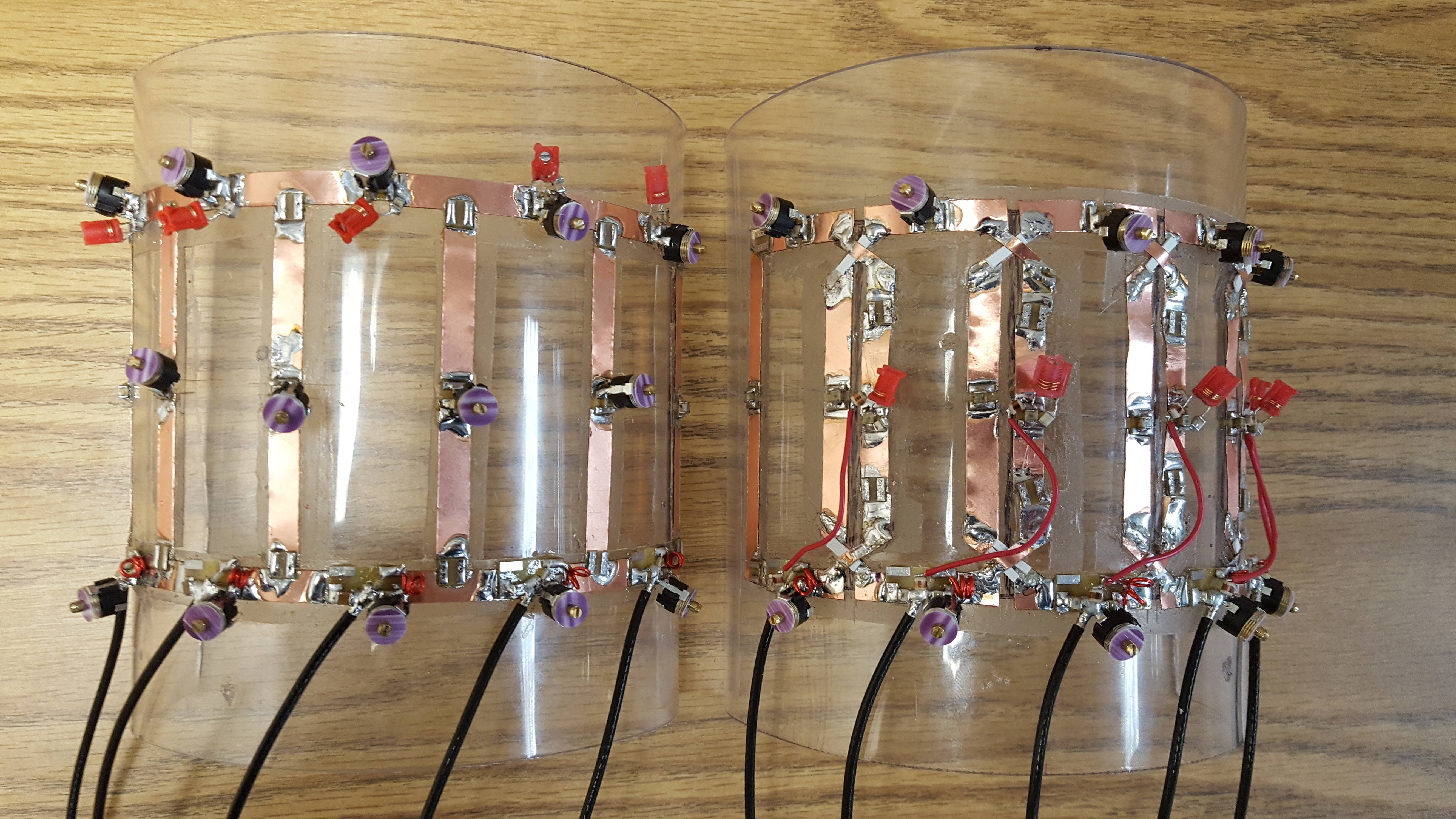
A 5-channel (5ch) ladder array and 5ch overlapped phased array were built using ¼ inch copper foil traces as shown in Fig 1. Both coils were constructed utilizing the same overall x and z dimensions of 15.5 cm x 8 cm, respectively. The coil element x and z dimensions were 3.1 cm x 8 cm and 3.35 cm x 8 cm for the ladder and overlapped arrays, respectively. All channels of both coils were actively decoupled. Isolation between adjacent elements of the ladder array was achieved with capacitive decoupling in the common leg between elements. The coils were built on a 3 mm thick cylindrical former with a 12.6 cm outer diameter. Each coil element was matched to 50 Ohms and was attached to a preamp via a 25 cm cable and pi phase shifter that completed a 180° phase shift for optimal preamp detuning. Imaging measurements were performed on the MAGNETOM 3T Prisma (Siemens Healthcare, Erlangen, DE) with a 12 cm diameter phantom (3.75g NiSO4 x 6H20 + 5g NaCl solution). Measured SNR results were compared against Bio-Savart simulations.Results
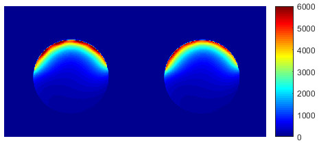
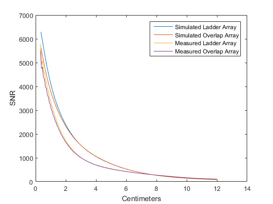
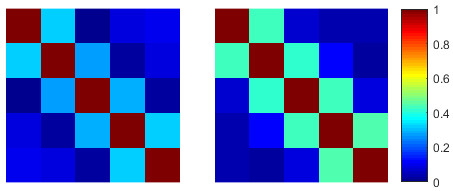
The sensitivity factor (Qunloaded to Qloaded ratio) of the coil elements was greater than 5 for all coil elements. This insured that the coils were sample noise dominated. The active decoupling for all the elements was greater than 40 dB. Preamp decoupling for all elements was at least 28 dB. These measurements were made using a double loop probe lightly coupled to the coil and measuring the difference between the resonant and loaded or decoupled state, respectively. SNR results3 comparing the ladder to the overlapped array are shown in Fig 2 and 3. An SNR line plot through the center of the SNR image in the anterior-posterior direction shows the ladder array has less than 3% difference in SNR from 2 to 12 cm deep in both the measured and simulated results. The correlation plots for the two constructed coil arrays are shown in Figure 4.Discussion
For the arrays to have the same outer dimensions the overlapped coil elements needed to be slightly larger to account for the overlap between loops. This resulted in the ladder array having greater SNR proximally. As shown in both the measured and simulation results, the difference in SNR at depth was negligible since the overall dimensions were the same and all coil elements were sample noise dominated. This comparison was limited to only 5 loops. For equal cost considerations in this comparison the number of elements and the outer dimensions of the array were held constant. The simulated and measured SNR results show the same trend, which is that the difference in SNR between the ladder and overlapped array is negligible at a depth greater than 2 cm.Conclusion
The SNR difference between the ladder and overlapped array was negligible. This indicates that coil arrays made with either technique with the same number of dimensions and outer dimensions should show little if any difference in performance. If the specific application allows for a ladder array, it could be considered due to the simplicity of the design and construction.Acknowledgements
No acknowledgement found.References
1. Roemer et al. The NMR phased array. Magn Reson Med 1990;16(2):192-225
2. Beck et al. Interchangeable Receive-Only Carotid Coils for Simultaneous Imaging with Radio Frequency Head Coils at 3 Tesla. 2016, ISMRM, Singapore.
3. Kellman et al. Image reconstruction in SNR units: a general method for SNR measurement. Magn Reson Med 2005;54(6):1439-1447.
Figures